40 iron carbon phase diagram explained
The difference between pig iron and cast iron Also called white cast iron (the fracture is white due to eutectic cementite). 3. Wrought iron: the carbon content is less than 0.008%, that is, to the left of point Q in the iron-carbon phase diagram, the carbon is solid-dissolved in the ferrite. The strength is very low, and it is generally only used as an electromagnet core. 4. en.wikipedia.org › wiki › MetalloidMetalloid - Wikipedia Hexagonal graphitic carbon (graphite) is the most thermodynamically stable allotrope of carbon under ambient conditions. It has a lustrous appearance and is a fairly good electrical conductor. Graphite has a layered structure. Each layer consists of carbon atoms bonded to three other carbon atoms in a hexagonal lattice arrangement.
Thermal Metastability of Pearlite in Iron-Carbon Alloys ... When tempering hardened steels, ε-carbide Fe 2 C that is absent in the phase diagram of alloys of the iron-carbon system is segregated in the structure of quenched martensite. It is generally accepted that ε-carbide Fe 2 C is not a stable phase. Since it is metastable, it is formed only in hardened steels under nonequilibrium conditions.

Iron carbon phase diagram explained
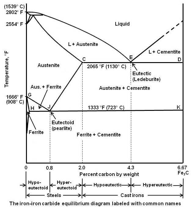
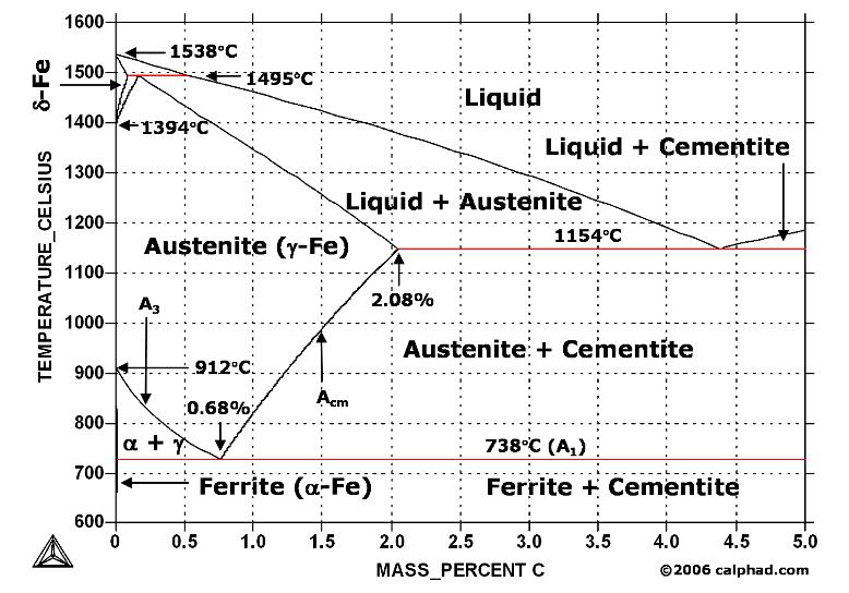
Phase Diagram - Industrial Metallurgists The phase diagram indicates that an iron-carbon alloy with 0.5% carbon held at 900 °C will consist of austenite, and that the same alloy held at 650 °C will consist of ferrite and cementite. Furthermore, the diagram indicates that as an alloy with 0.78% carbon is slow cooled from 900 °C, it will transform to ferrite and cementite at about 727 °C. Adsorption Isotherm (Theory) - Amrita Vishwa Vidyapeetham This can be explained on the basis of a possibility of gases getting condensed in the tiny capillary pores of adsorbent at pressure below the saturation pressure (P S) of the gas. Examples of Type IV Adsorption Isotherm are of adsorption of Benzene on Iron Oxide (Fe 2 O 3) at 500°C and adsorption of Benzene on silica gel at 500°C. Hooke's law: definition, formulae, stress-strain curve ... Stress-strain diagram for brittle material. The figure below shows the stress-strain diagram of a brittle material, say for eg. cast iron. Some examples of brittle material are ceramics, cast iron, high carbon steel, etc. You are free to use this image, appropriate attribution with a link to the post is required.
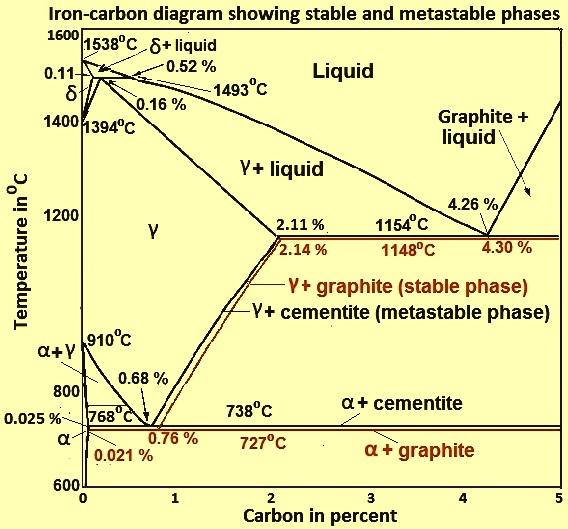
Iron carbon phase diagram explained. Microstructure formation of steels during ... - tec-science 30/06/2018 · Therefore, the phase diagram of the iron/carbon alloy system is somewhat more complex. In order to understand the microstructural processes inside a steel, it makes sense to first take a closer look at the microstructure formation of pure iron. For this reason, the cooling curve of iron is discussed in more detail in the following section. Microstructure formation of … The Carbon Border Adjustment Mechanism explained ... The most contentious proposal from an international point of view is the Carbon Border Adjustment Mechanism (CBAM), which aims to create a level playing field for EU producers subject to EU carbon pricing. The CBAM foresees in an import levy on EU imports of electricity, cement, aluminium, fertilizer and iron and steel products, depending on ... Gas Chromatography - Principle, Application, Procedure and ... Stationary phase - It is either in the forms of solid adsorbent (gas-solid chromatography) or liquid on an inert support (gas-liquid chromatography).; Mobile phase - It is a chemically inert gas that carries analyte molecules through the heated column.; The gas chromatography is the only form of chromatography that does not use the mobile phase when interacting with the analyte. HW9 Solutions - Homework 9 - CHAPTER 9 PHASE DIAGRAMS ... From Figure 9 (the Cu-Zn phase diagram), which is shown below with a vertical line constructed at the specified composition: At 1000 C, a liquid phase is present; WL = 1. At 800 C, the phase is present, and W = 1. At 500 C, and phases are present, and from the tie lie constructed on the above diagram W = C 0 - C C - C = 52 - 49 58 - 49 =0.
› science › articleExperimental study of stratification behavior of the steady ... The micro-structure and phase analysis has been made for metallic and oxide phases of all ingots, as shown in Fig. 4, Fig. 5, Fig. 6 and Table 4. What needs to be explained here is that since the carbon steel rings used for ignition are added in tests #1 and #2, some impurity elements such as C and Cr may be introduced. The Fe-FeSi phase diagram at Mercury's core conditions ... Both scenarios are found either in the Fe-Si phase diagram at ambient pressure 49, or related iron-based alloys, e.g., Fe-V, 35. At higher pressures, the hcp + B2 region expands in temperature to... GATE & ESE - Iron Carban Phase Diagram I Material Science ... Iron Carban Phase Diagram I Material Science I GATE ME 2022. Nov 25, 2021 • 1h 22m . Shahpar Ayaz. 811K watch mins. In this Course Shahpar Ayaz Sir is going to discuss very important topic of Material Science ( Iron Carban Phase Diagram ) Watch Now. Share. Hindi ECE. Similar Classes. Steel Cooling Curve - heating and cooling curves worldwise ... Steel Cooling Curve - 13 images - print definitions of element mixture alloy molecule and, shop home styles 52 in l x 25 in w x 36 in h powder coated, heat treatment of steels united induction heating machine, heat treatment goel steel company,
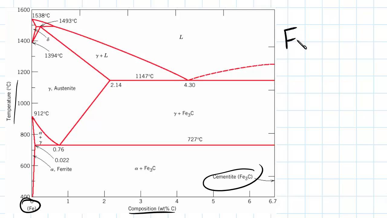
Phase Diagrams: Critical Point, Triple Point and Phase ... They are the lines on a phase diagram where two phases are in equilibrium. One line shows the equilibrium point between solid and liquid. One shows the equilibrium point between liquid and gas. The... Experimental Investigation on Carbon Diffusion at the ... The Fe-Fe 3 C phase diagram can be used to explain the mechanism of carbon diffusion. 20 Figure 1 b shows this diagram (FactSage 7.0) where the contents of Mn and Si are set to 0.391 wt.% and 0.11 wt.%, respectively. The original conditions of the hot metal and scrap cylinder are ( Cb, Tb) and ( Cs, Ts ), respectively. 7.4: Iron and Steel - Chemistry LibreTexts The iron-iron carbide (Fe-Fe 3 C) phase diagram. Below 912 °C, pure iron exists as the alpha phase, ferrite, which has the BCC structure. Between 912 and 1,394 °C, pure iron exists as the gamma phase, austenite, which has the FCC structure. Magic Lab The underlying causes are uncovered by thermodynamic and phase diagram analyses. Our research reveals the thermodynamic driving forces underlying the unconventional high-capacity Fe-poor ferrites, further explained via phase diagrams of Fe-Co-O, Fe-Ni-O and Fe-Mg-O. Future materials improvements can be guided by our reduced Gibbs ...
Iron-carbon phase diagram |
AISI/SAE 1010 Steel - Composition, Properties and Applications Microstructure of 1010 Steel. 1010 steel is low carbon steel and mechanical properties can easily be understood from TTT diagram and iron-iron carbide diagram.You can check articles on how the microstructure can generate variation in mechanical properties. If we summarize structure, then 1010 steel is basically in hypo-eutectoid region, major portion characterized as ferritic region.

7 Iron carbon phase ideas | carbon, mechanical engineering, iron
Calvin Cycle - an overview | ScienceDirect Topics Calvin cycle also known as Calvin-Benson-Bassham or reductive pentose pathway has been the first CO 2 fixation cycle discovered by Calvin, Benson and Bassham in plants and after reported in many other microorganisms [24–26].In this cycle represented in Fig. 18.1, ribulose-1,5-biphosphate carboxylase oxygenase (RuBisCO), a key enzyme of this process, sequesters a …

IRON-CARBON PHASE DIAGRAM (PT1) How to build the phase diagram
3 Wire Alternator Wiring Diagram 🏎️ What Wires Go Where? The three-wire alternator wiring diagram is used in the car, as you know that now. The stator and rotor are two elements of a three-wire alternator wiring diagram. The three-phase armature winding is found in the stator, while field winding is found in the rotor. We know that batteries can only hold DC.

Iron Carbon phase diagram | Download Scientific Diagram
Isentropic ("adiabatic") process in a closed system - tec ... Isentropic ("adiabatic") process in a closed system An isentropic process is a reversible process of an adiabatic system. 1 Definition 2 How to achieve an approximately isentropic process 3 Illustration in the volume-pressure diagram 4 Relationship between volume, pressure and temperature 5 Calculation of the change in internal energy

Iron-Carbon Equilibrium Phase Diagram (Gonzalez, 2008 ...
Carbon - Wikipedia Theoretically predicted phase diagram of carbon, from 1989. Newer work indicates that the melting point of diamond (top-right curve) does not go above about 9000 K. The allotropes of carbon include graphite, one of the softest known substances, and diamond, the hardest naturally occurring substance.
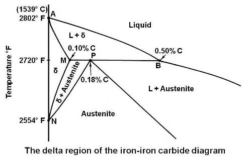
Practical Maintenance » Blog Archive » The Iron-Iron Carbide ...
Grey, blue, green - the many colours of hydrogen explained ... Yes / No. There are many 'colours' of hydrogen - each referring to how it is produced. Green hydrogen is the only variety produced in a climate-neutral manner. It could play a vital role in global efforts to reach net-zero emissions by 2050. Green hydrogen has been hailed as a clean energy source for the future.

Iron –carbon phase diagram
Evolving Highly Active Oxidic Iron(III) Phase from ... This new phase is structurally disordered (PXRD amorphous) and consists of [FeO 6] octahedra which are connected via edge (70%) and corner sharing (30%). Even though around 50% of the FeSi transformed, only 30% of the silicon leached. Therefore, the oxidic iron(III) phase still contains 40% of the initial silicon.
IRON –CARBON PHASE DIAGRAM
The Ocean's Biological Pump - Climate and the Carbon Cycle Oceans and the Carbon Cycle Part A: Down to the Deep - The Ocean's Biological Pump. Oceans have a large capacity to absorb CO 2, thus reducing the amount of CO 2 in the atmosphere and bringing carbon atoms into the ocean system. Many CO 2 molecules that diffuse into sea surface waters diffuse back to the atmosphere on very short time scales. However, some of the carbon atoms from these ...
Introduction to Iron Carbon Phase Diagram | Engineering Materials
Derivation of the formulas for work and heat of a ... The pressure-volume work W v can generally be calculated by integrating the p (V) function of the polytropic process: Wv = - V2 ∫ V1p(V) dV. Thus, for calculating the work, the function p (V) must be known. If a polytropic process is mathematically described starting from an initial state 1 with pressure p 1 and volume V 1, equation ( 1 ...
Iron Carbon Phase or Equilibrium Diagram or Iron Carbide ...
Thermodynamic Principles of Metallurgy - GeeksforGeeks Because the carbon line crosses the lines of many metal oxides, it can decrease all of them at sufficiently high temperatures. Let's look at the thermodynamically favourable circumstances for iron oxide reduction by carbon. Around 1000 K, the Ellingham diagram for the production of FeO and CO intersects.

Phase Diagram - Industrial Metallurgists
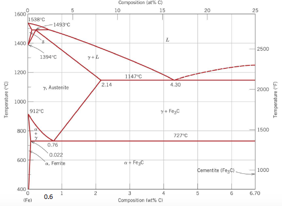
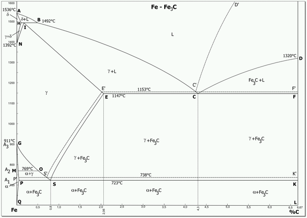
Iron Carbon Equilibrium Diagram with Explanation [Phase ... The Iron carbon equilibrium diagram (also called the iron carbon phase diagram) is a graphic representation of the respective microstructure states of the alloy iron - carbon (Fe-C) depending on temperature and carbon content. The iron carbon phase diagram is commonly used to fully understand the various phases of steel and cast iron.
IRON –CARBON PHASE DIAGRAM
(Solved) - 1.Compute the volume percent of graphite, VGr ... 1.Compute the volume percent of graphite, VGr, in a 2.5 wt% C cast iron, assuming that all the carbon exists as the graphite phase. Assume desities of 7.9 and 2.3 g/cm3 for ferrite and graphite, respectively 2. On the basis of microstructure, briefly explain why gray iron is brittle and weak in tension Sep 10 2021 03:04 PM 1 Approved Answer
The Iron-Carbon Phase Diagram – IspatGuru
Transformation of Graphite to Diamond - Thermodynamics The phase diagram of carbon is shown in Fig. 5.5. At low pressure, graphite is stable at all temperatures up to the melting point. In order to transform graphite into diamond at constant temperature, the pressure must be very high. This is how, deep under the earth, diamond was created.
crystal structure - Having trouble understanding the iron ...
4.6: Pourbaix Diagrams - Chemistry LibreTexts The corrosion of iron (and other active metals such as Al) is indeed rapid in parts of the Pourbaix diagram where the element is oxidized to a soluble, ionic product such as Fe 3+ (aq) or Al 3+ (aq). However, solids such as Fe 2 O 3, and especially Al 2 O 3, form a protective coating on the metal that greatly impedes the corrosion reaction.

Welding , Hardfacing , Cladding and Cutting of metals ...
Iron - Wikipedia Iron-carbon phase diagram. Types of steels and alloys. α-Iron is a fairly soft metal that can dissolve only a small concentration of carbon (no more than 0.021% by mass at 910 °C). Austenite (γ-iron) is similarly soft and metallic but can dissolve considerably more carbon (as much as 2.04% by mass at 1146 °C). This form of iron ...
3 The true equilibrium iron-carbon phase diagram with ...
(Get Answer) - Binary phase diagram question The following ... The iron-carbon phase diagram is shown below. Please answer the following questions (i) What are the composition (i.e. how much wt % C) and temperatures corresponding to the Eutectic and the Eutectoid points Eutectic: Eutectoid (ii) When a 30 wt %...
Iron-Carbon Phase Diagram (a review) see Callister Chapter 9
Hooke's law: definition, formulae, stress-strain curve ... Stress-strain diagram for brittle material. The figure below shows the stress-strain diagram of a brittle material, say for eg. cast iron. Some examples of brittle material are ceramics, cast iron, high carbon steel, etc. You are free to use this image, appropriate attribution with a link to the post is required.

The Iron Carbon Phase Diagram
Adsorption Isotherm (Theory) - Amrita Vishwa Vidyapeetham This can be explained on the basis of a possibility of gases getting condensed in the tiny capillary pores of adsorbent at pressure below the saturation pressure (P S) of the gas. Examples of Type IV Adsorption Isotherm are of adsorption of Benzene on Iron Oxide (Fe 2 O 3) at 500°C and adsorption of Benzene on silica gel at 500°C.

Cast Iron; 9.5.1 General Remarks
Phase Diagram - Industrial Metallurgists The phase diagram indicates that an iron-carbon alloy with 0.5% carbon held at 900 °C will consist of austenite, and that the same alloy held at 650 °C will consist of ferrite and cementite. Furthermore, the diagram indicates that as an alloy with 0.78% carbon is slow cooled from 900 °C, it will transform to ferrite and cementite at about 727 °C.
Solidification of steels

Iron carbon equilibrium diagram with explanation. ||Engineer's Academy||

Delta Iron - an overview | ScienceDirect Topics
Iron-Carbon Phase Diagram Steel Cementite PNG, Clipart, Angle ...

Please answer the following question regarding the iron-iron ...

Iron-Carbon Equilibrium Phase Diagram ... | Diagram ...
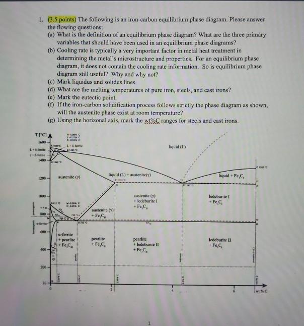
Solved 1. (3.5 points) The following is an iron-carbon ...
The Iron - Iron Carbide (Fe-Fe C) Phase Diagram
The C-Fe (carbon-iron) system

4 Iron-Carbon phase diagram | Download Scientific Diagram
The C-Fe (carbon-iron) system
Consider Iron-carbon phase diagram given below: (a) | Chegg.com
Material Science, The Iron Carbon Phase Diagram, Part 1
The iron-iron carbide (Fe-Fe3C) phase diagram Microstructures ...
![Iron-Carbon Diagram Explanation [PDF]](https://mechanicalenotes.com/wp-content/uploads/2018/10/Iron-Carbon-Phase-diagram-feature-image.png)
Iron-Carbon Diagram Explanation [PDF]
The Iron - Iron Carbide (Fe-Fe C) Phase Diagram
Practical Maintenance » Blog Archive » The Iron-Iron Carbide ...
Iron-carbon phase diagram

Teach Yourself Phase Diagrams

Metallurgical engineering - The Iron Carbon Phase Diagram ...
phase diagram iron carbon | Metallurgy for Dummies


Comments
Post a Comment