38 what is collaboration diagram in uml
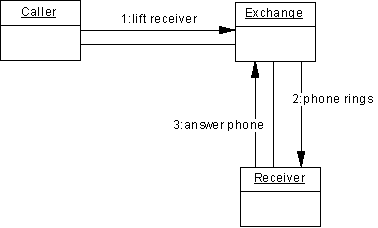
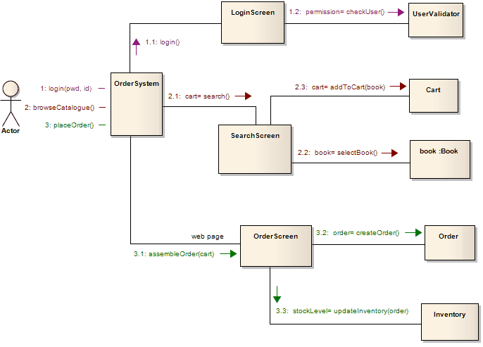
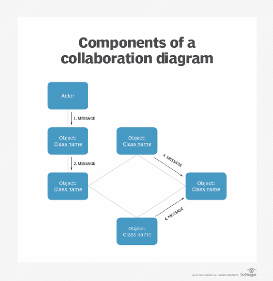
UML collaboration diagrams are great tools for documenting the flow of messages between objects while providing a unique perspective?a view of the relationships between collaborating objects. At the very heart of any complex software application are business objects. As the user interacts with the software, business objects respond by carrying ... UML communication diagrams, like the sequence diagrams - a kind of interaction diagram, shows how objects interact. A communication diagram is an extension of object diagram that shows the objects along with the messages that travel from one to another. In addition to the associations among objects, communication diagram shows the messages the objects send each other.
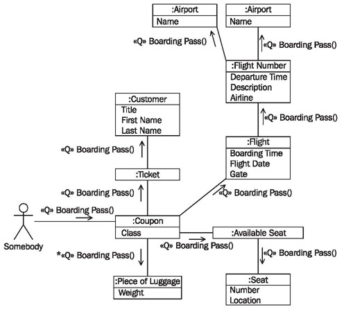
A collaboration diagram is a type of Unified Modeling Language (UML) interaction diagram that highlights the structural organization of objects in Object Oriented Programming (OOP) computer system design. The collaboration diagram depicts the relationships of objects to each other. These diagrams can require technical skill and training to create.
What is collaboration diagram in uml
UML Collaboration Diagram. The collaboration diagram is used to show the relationship between the objects in a system. Both the sequence and the collaboration diagrams represent the same information but differently. Instead of showing the flow of messages, it depicts the architecture of the object residing in the system as it is based on object ... Collaboration diagrams (known as Communication Diagram in UML 2.x) are used to show how objects interact to perform the behavior of a particular use case, or a part of a use case.Along with sequence diagrams, collaboration are used by designers to define and clarify the roles of the objects that perform a particular flow of events of a use case. A communication diagram in the Unified Modeling Language (UML) 2.0, is a simplified version of the UML 1.x collaboration diagram.. UML has four types of interaction diagrams: Sequence diagram; Communication diagram; Interaction overview diagram; Timing diagram; A Communication diagram models the interactions between objects or parts in terms of sequenced messages.
What is collaboration diagram in uml. Difference SEQUENCE DIAGRAMS COLLABORATION DIAGRAMS The sequence diagram represents the UML, which is used to visualize the sequence of calls in a system that is used to perform a specific functionality. The collaboration diagram also comes under the UML representation which is used to visualize the organization of the objects and their interaction. The sequence diagram are used to represent ... Read on to learn more about what UML is, the types of UML diagrams, and how to use a UML diagram to benefit your collaboration. What is a UML Diagram? UML stands for Unified Modeling Language , and it is a modeling language that is most often used for software engineering but has extended its use to business process es and other project workflows. UML diagram is a model that describes a part of a system. It is used to define the functionality or a design of a system. A diagram must be clear and concise so that the viewer will readily understand it. UML diagrams are divided into three different categories such as, Structural diagram. Behavioral diagram. A Sequence diagram is an interaction diagram that details about the operation that is carried out. The sequence diagram captures the interaction between the objects in the context of collaboration. Sequence diagrams are time focused and they show the order of the interaction visually by using the vertical axis of the diagram to represent time.
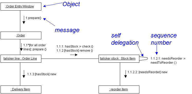
Interaction Diagrams §UML Interaction Diagramsrefine the kind of activity undertaken in checking with CRC cards §There are two different kinds of interaction diagrams: • Collaboration Diagrams • Sequence Diagrams §There is some redundancy between Collaboration and Sequence Diagrams • They differently show how elements interact over time The UML diagram is a general-purpose way to visualize the main concepts of object-oriented concepts used in the software. It is the blueprint of the software architecture. The ER diagram is the pictorial representation of the objects and their relationships. Relationships. The UML diagram is the superclass of the ER diagram. Important: The UML Collaboration diagram is not available in Visio 2013 and newer versions. For information on UML diagrams in Visio 2013 and newer versions, see UML diagrams in Visio . In a Classifier Role shape, the object's designator string is underlined to indicate that the object is an instance. The collaboration diagram and sequence diagram shows similar information but in a distinct form. It can portray the architecture of an object inside the system. It can be used to depict the relationship among various objects within the system.
UML Collaboration. Collaboration extends both behaviored classifier and structured classifier to explain how a collection of cooperating instances achieve a joint task or set of tasks. Its primary purpose is to explain how a system works and, therefore, it typically only incorporates those aspects of reality that are deemed relevant to the explanation. Our UML diagram tool facilitates the design and documentation processes but also improves how you collect, review, and implement feedback from stakeholders or potential users. Lucidchart is built for real-time collaboration, helping you refine your UML diagrams … UML Tutorial for C++ - Windows Platform GDPro 5.0-1-©2000 Advanced Software Technologies, Inc. Chapter 7 : Collaboration Diagram The Collaboration Diagram What is a Collaboration Diagram • Cross between an symbol diagram and a sequence diagram • Describes a specific scenario UML Sequence Diagram with What is UML, OO Analysis and Design, Building Blocks, Architecture, Diagrams, Relationships, Object Diagram, Component Diagram, Tools ...
08.10.2021 · Collaboration diagram; Timing diagram; UML Component Diagram; Deployment Diagram; Things in UML . A thing can be described as any real-world entity or an object. Things are divided into various categories in UML as follows, Structural things; Behavioral things; Grouping things; Annotational things ; Structural things. Structural things are all about the physical part of a system. It is …
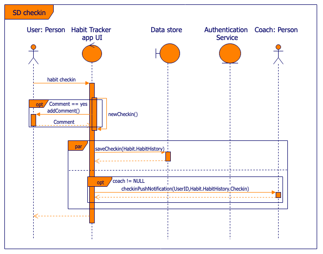
This interactive behavior is represented in UML by two diagrams known as Sequence diagram and Collaboration diagram. The basic purpose of both the diagrams are similar. Sequence diagram emphasizes on time sequence of messages and collaboration diagram emphasizes on the structural organization of the objects that send and receive messages. Purpose of Interaction Diagrams. The …
Modeling Technique Uml The Unified Modeling Language Uml Has Evolved Into An Industry Standard For Documenting The Components Of An Object Oriented System The Construction Of A Model That Maps To The Real World Object Is Half The Solution To The
The UML collaboration diagram can be illustrated by designing objects in a structure and illustrating the connections between the objects as links. Given below is a step-by-step guide to creating a collaboration diagram with Edraw Max. Step 1: Open a UML Diagram template. Click on new, select Software and then pick UML Model Diagram. ...
UML Diagram Tool The Better Way to Create UML Diagrams The easiest set of tools for creating complex UML diagrams and models for software teams. Understand source code, plan new features, and visualize flows and tasks within your system.
The Collaboration Diagram in UML is also called a communication diagram. The purpose of a collaboration diagram is to emphasize structural aspects of a system, i.e., how various lifelines in the system connects. Timing diagrams focus on the instance at which a message is sent from one object to another object.
A communication diagram in the Unified Modeling Language (UML) 2.0, is a simplified version of the UML 1.x collaboration diagram. They are one and the same. Share
Communication diagrams, formerly known as collaboration diagrams, are almost identical to sequence diagrams in UML, but they focus more on the relationships of objects—how they associate and connect through messages in a sequence rather than interactions.
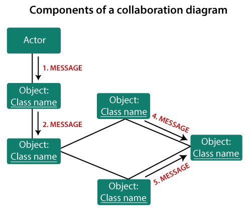
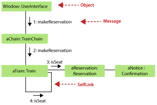
A collaboration diagram, also known as a communication diagram, is an illustration of the relationships and interactions among software objects in the Unified Modeling Language ().These diagrams can be used to portray the dynamic behavior of a particular use case and define the role of each object.. Collaboration diagrams are created by first identifying the structural elements required to ...
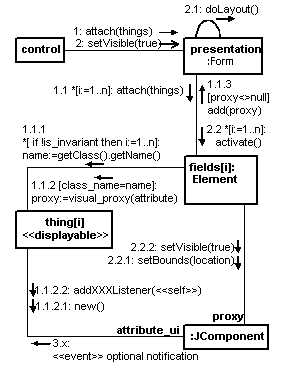
UML Collaboration Diagrams Use a collaboration diagram (collaboration diagram: An interaction diagram that shows, for one system event described by one use case, how a group of objects collaborates with each other.) to show relationships among object roles such as the set of messages exchanged among the objects to achieve an operation or result.. UML Collaboration diagrams (interaction ...
Sequence diagram of a hospital management system. Technology has completely transformed the field of medicine, as it has with most industries. A hospital information system, also known as a hospital information system, helps doctors, administrators, and hospital staff managing all of the activities and information collected at a hospital, including checkups, prescriptions, appointments, and ...
Unified Modeling Language (UML) is a general purpose modelling language. The main aim of UML is to define a standard way to visualize the way a system has been designed. It is quite similar to blueprints used in other fields of engineering. UML is not a programming language, it is rather a visual language. We use UML diagrams to portray the ...
31.08.2021 · UML Collaboration Diagram Purpose A collaboration diagram is used to describe a collection of objects that interact to implement some behavior within a context. It's used to model system functionality, which is more specifically, visualize the relationship between objects collaborating to perform a particular task and model the logic of the implementation for a complex operation. Usage The ...
The Unified Modeling Language (UML) is an analysis and design specification that defines the diagrams, the graphical notation and syntax for describing and documenting software designs. In November of 1997, the UML was adopted by the OMG (Object Management Group) standards committee and quickly became the universal modeling language.
The next in the dynamic diagrams in UML that we will cover is the Collaboration Diagram. Basics. In the previous article, we covered the basics of a Sequence diagram. A Sequence diagram is dynamic, and, more importantly, is time ordered. A Collaboration diagram is very similar to a Sequence diagram in the purpose it achieves; in other words, it ...
UML Communication Diagrams, previously known as collaboration diagrams are a type of behavioural diagram that shows the interactions that take place between objects in a piece of software or system. This type of diagram emphasizes the messages exchanged between objects. Communication diagrams are best used when one use case has multiple ...
In many ways, a communication diagram is a simplified version of a collaboration diagram introduced in UML 2.0. State Diagram Statechart diagrams , now known as state machine diagrams and state diagrams describe the dynamic behavior of a system in response to external stimuli.
A communication diagram in the Unified Modeling Language (UML) 2.0, is a simplified version of the UML 1.x collaboration diagram.. UML has four types of interaction diagrams: Sequence diagram; Communication diagram; Interaction overview diagram; Timing diagram; A Communication diagram models the interactions between objects or parts in terms of sequenced messages.

Uml Collaboration Diagram Uml2 0 Uml Collaboration Diagram Design Elements Diagramming Software For Design Uml Collaboration Diagrams Uml Communication Diagram
Collaboration diagrams (known as Communication Diagram in UML 2.x) are used to show how objects interact to perform the behavior of a particular use case, or a part of a use case.Along with sequence diagrams, collaboration are used by designers to define and clarify the roles of the objects that perform a particular flow of events of a use case.
UML Collaboration Diagram. The collaboration diagram is used to show the relationship between the objects in a system. Both the sequence and the collaboration diagrams represent the same information but differently. Instead of showing the flow of messages, it depicts the architecture of the object residing in the system as it is based on object ...









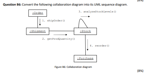
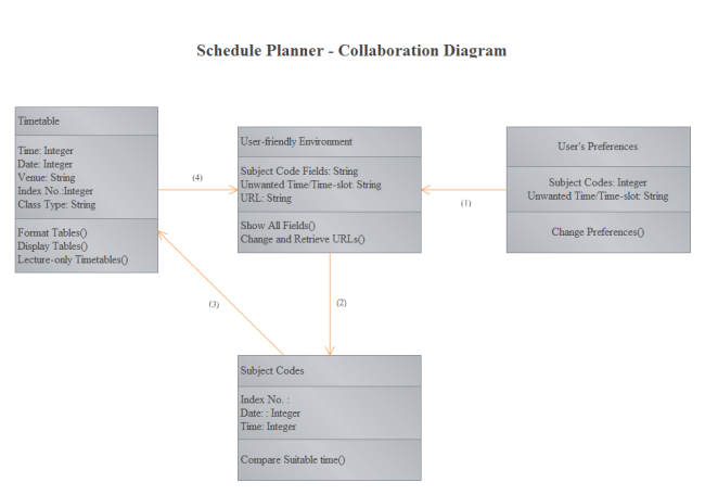

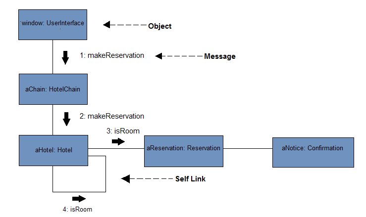
Comments
Post a Comment