40 door lock relay diagram
Feb 3, 2015 - Power Door Locks: Connecting to Multiple Wire Door Lock Systems, Types A, B, C, D, and E, Add Auto Lock/Unlock. press secondary button to unlock all doors at once - alarm disarmed. 10Amp 86 87 85 87a 30 RELAY #1 BOOT RELEASE LOCK UNLOCK REL-003 CONFIGURATIONS DUAL DOOR ...
How to Wire Automotive SPDT Relays. Door Locks - 3 Wire Positive (Type A). This is one of the most common type of door lock switch configurations found in ...
Door lock relay diagram
Magnetic door locks can only be in fail-safe mode when power is cut off. The Safety to Relay can be connected to a door managed by the ACM system. The diagram ( ... INTERFACES WITH ALL REMOTE CONTROL SYSTEMS WITH (-) PULSED DOOR LOCK OUTPUTS. 3-PIN PLUG INTERFACE WITH DEI SYSTEM. BUILT IN RELAY WIRING HARNESS. WHITE/BLK.3 pages 5 Oct 2021 — TThe user can also manage the power supply of the electric lock ... Schematic diagram of connecting the Relay to a 12/24-volt electric lock.
Door lock relay diagram. (114.3 x 127 x 50.8 mm). INSTALLATION INSTRUCTIONS - MODEL UR2-4. UNIVERSAL DOOR CONTROLLER. Centralized wiring for all locks, access controls, monitoring.17 pages 5 Oct 2021 — TThe user can also manage the power supply of the electric lock ... Schematic diagram of connecting the Relay to a 12/24-volt electric lock. INTERFACES WITH ALL REMOTE CONTROL SYSTEMS WITH (-) PULSED DOOR LOCK OUTPUTS. 3-PIN PLUG INTERFACE WITH DEI SYSTEM. BUILT IN RELAY WIRING HARNESS. WHITE/BLK.3 pages Magnetic door locks can only be in fail-safe mode when power is cut off. The Safety to Relay can be connected to a door managed by the ACM system. The diagram ( ...
How to wire door lock relays for aftermarket actuators. - YouTube

1994 s10 Blazer 4 door. The power door locks are engaging ...
power door locks on dodge dakota

RFID Based Solenoid Door lock using Arduino
magnetic door lock – tlfong01.blog

SPAL Power Lock actuator with Viper 350(3105) relay wiring ...
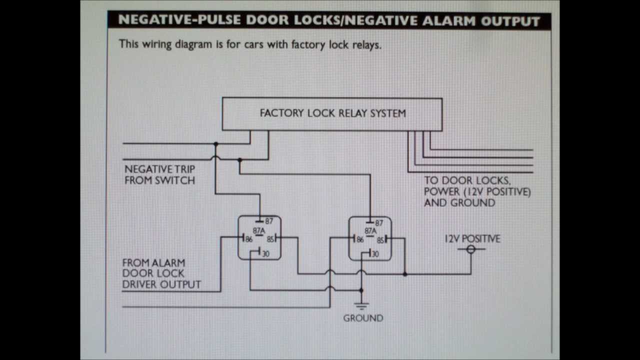
How To Wire Your Alarm To A Car With Negative Door Lock ...

Door Lock Wiring Relay Diagram - Dodge Cummins Diesel Forum
Power Door Lock Relay - Power Lock
Car Security and Convenience, Power Door Locks, Multiple ...
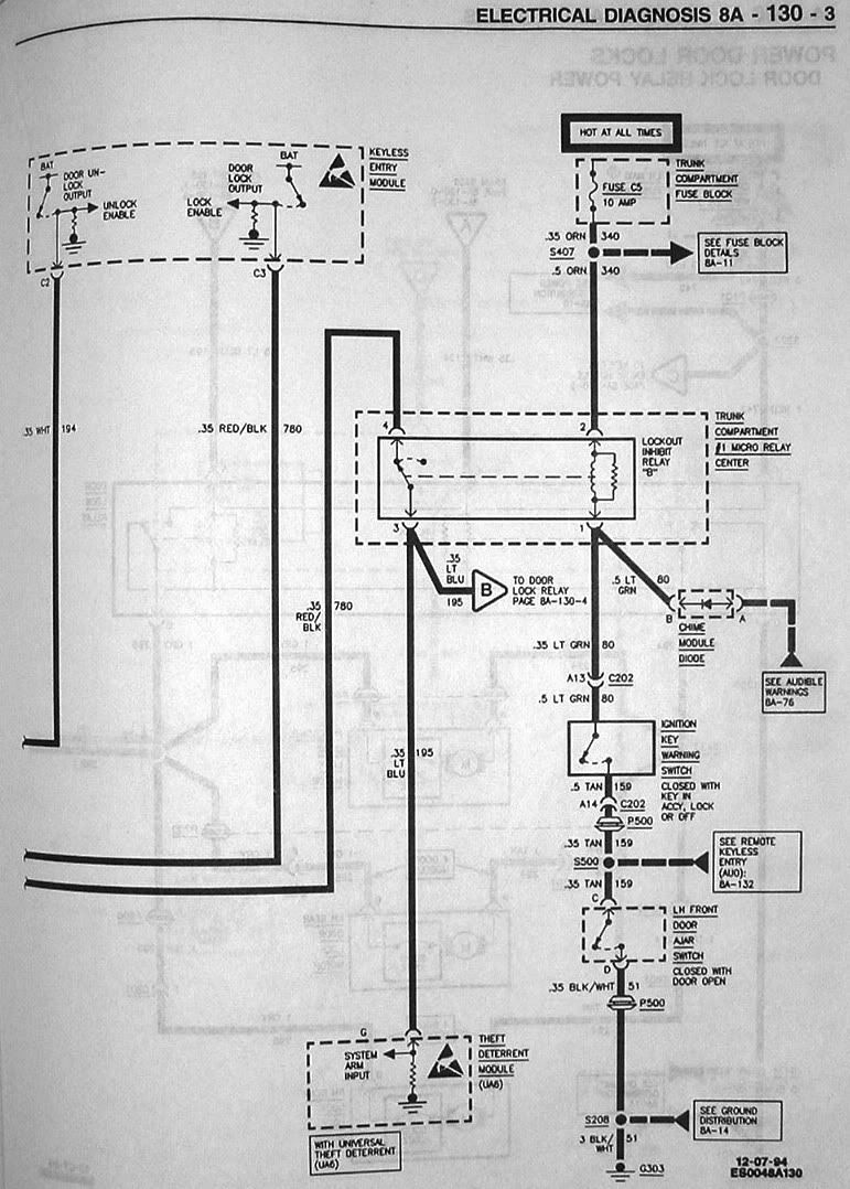
Chevrolet Astro 2001 Door Lock Relay Electrical Circuit ...
95 Seville Power Locks - Page 2

I have a 2001 F250 pick up and the door locks are not ...
Door Locks - Ford Probe (Type G) Relay Wiring Diagram
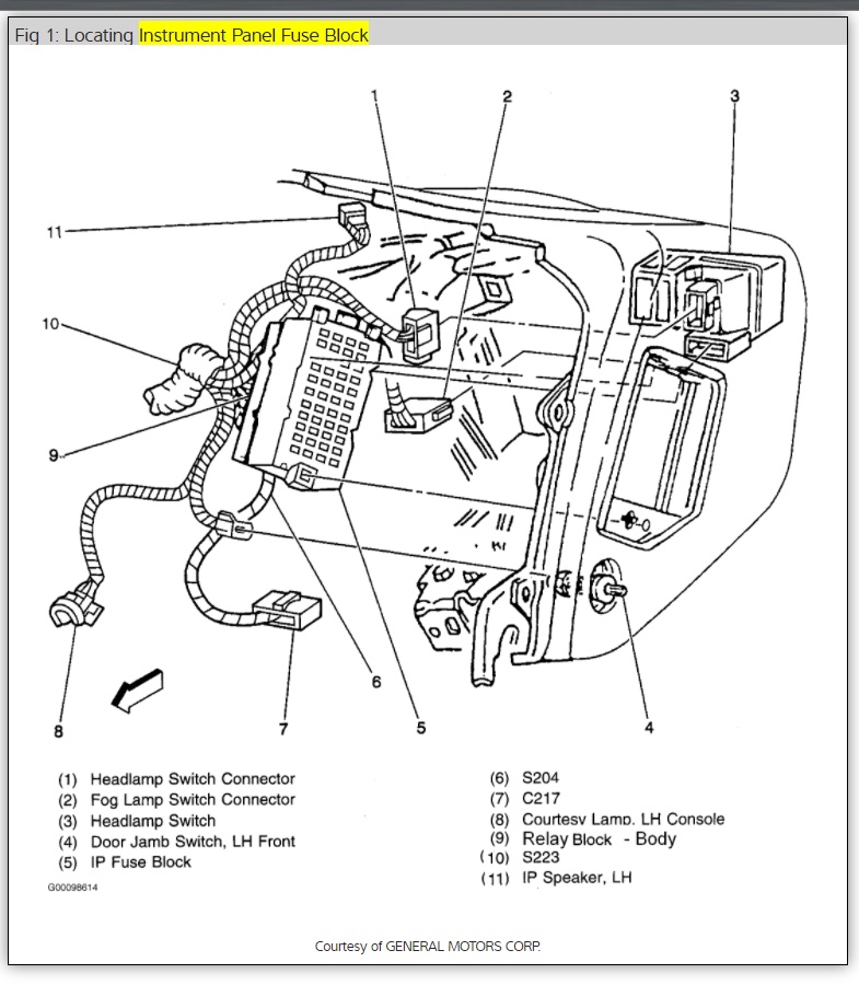
Where I The Power Door Lock Relay Located On A 1998 Chevy ...
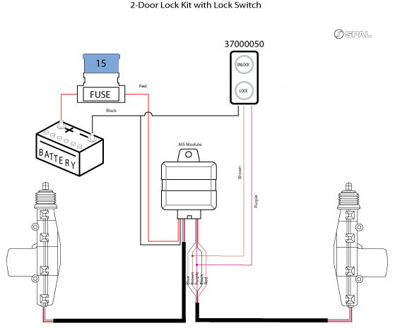
SPAL Power Lock actuator with Viper 350(3105) relay wiring ...

Power Door Lock Install on a Jeep Wrangler YJ

Relay circuit

Relay circuit

Where do I find the relay for the power door locks on a 99 ...

31 5 Wire Door Lock Relay Diagram - Worksheet Cloud

Doors lock while in gear - Nissan Titan Forum

Aftermarket keyless entry install help 97 - Ford F150 Forum
Ford Workshop Manuals > Probe L4-133 2.2L SOHC Turbo (1989 ...
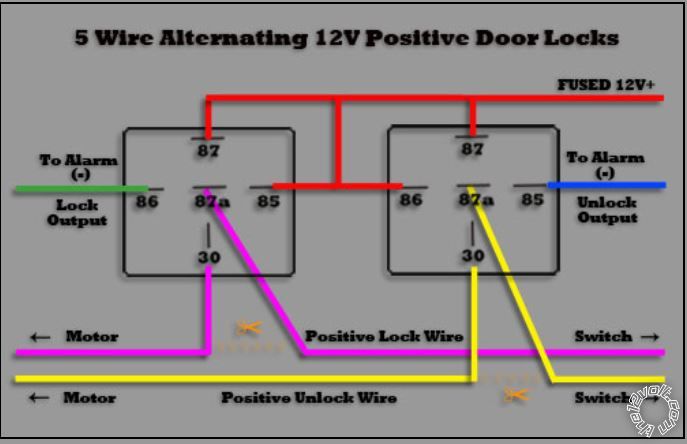
30 5 Wire Door Lock Relay Diagram - Free Wiring Diagram Source

Toyota MR2 Relay, power steerin. Electrical, usa, switch ...

31 5 Wire Door Lock Relay Diagram - Wiring Diagram Database
Single Wire Power Door Lock Systems, Type F, Type G, Type H
Door Lock Wiring

| Repair Guides | Power Door Locks (2000) | Power Door ...

Door Diagram & Combination Screen \u0026 Storm Doors""sc ...
Relays on power door locks-Fully operational death star! - Full Size Jeep Network

100 reasons Leo Frank is Guilty - Audiobook


Comments
Post a Comment