41 freightliner speedometer wiring diagram
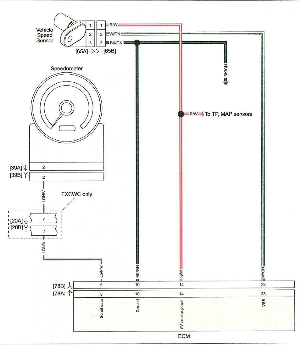
Notes: High resolution diagram/schematic download. The 1992-2007 Freightliner/Sterling Cargo Truck Wiring Diagrams provide information for the correct servicing and troubleshooting of electrical systems and is essential for all mechanics carrying out wiring repairs on 1992-2007 Freightliner/Sterling Cargo Trucks. i. Connect the other black wire to a ground (other than the speedometer ground) b. Terminal "6" on a 4-5/8" speedometer. 6) Connect the speed signal to the "SIG" or "3" terminal on the back of the speedometer: a. White wire from a Classic Instruments signal generator (SN16 or SN16F) b. Output from a SN74 speedometer calibration box
Description : Freightliner Headlight Wiring Diagram In Proxy inside Freightliner Headlight Wiring Diagram, image size 1024 X 663 px, and to view image details please click the image. Here is a picture gallery about freightliner headlight wiring diagram complete with the description of the image, please find the image you need.
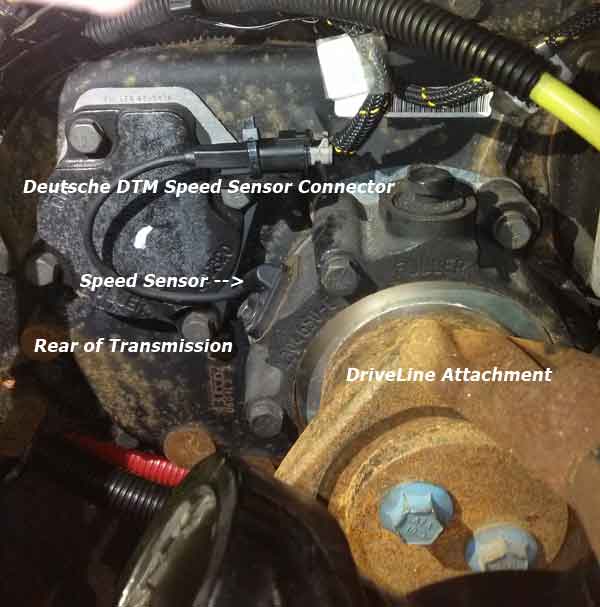
Freightliner speedometer wiring diagram
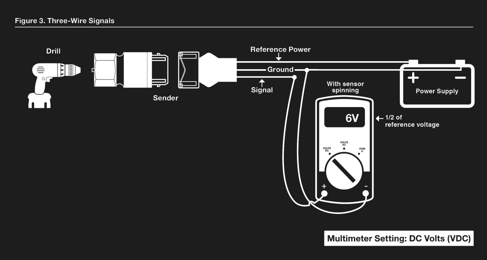
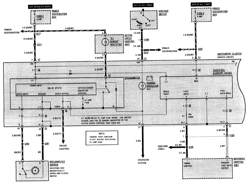
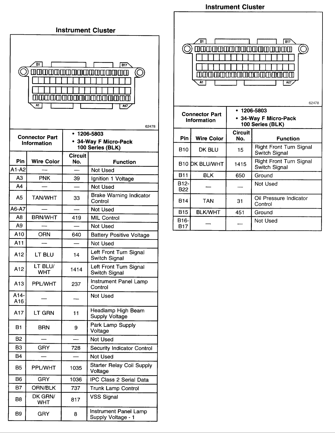
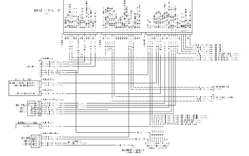
The new information is that it is a SINGLE WIRE OUTPUT. He also confirmed that, unless there are other symptoms (like the Allison going bananas), the sensor itself is good. Freightliner wiring digram shows the "J2" connector from the TCM and shows pin 26 going to "transmission interface connector" in the wiring diagram. The speedometer does not work have change many parts to include Accelerator pedal, body control module, chassis control module, TCM, speed sensors, input and output sensors, no codes just don't have a wiring diagram for the instrument cluster to see which is the speedo wire or where it goes to. no one can seem to help me I have checked ... Freightliner Speedometer Wiring Diagram - wiring diagram is a simplified okay pictorial representation of an electrical circuit. It shows the components of the circuit as simplified shapes, and the aptitude and signal links in the midst of the devices. A wiring diagram usually gives suggestion approximately the relative aim and treaty of ...
Freightliner speedometer wiring diagram. New Freightliner Speedometer Wiring Diagram. By Rendra Posted on September 18, 2018. September 18, 2018. New Freightliner Speedometer Wiring Diagram. - Welcome to help my blog, on this occasion I will teach you regarding freightliner speedometer wiring diagram. . And now, here is the first picture: Cool 06 Freightliner Columbia Wiring ... Navistar International Truck C ircuit Diagrams . PDF Files. Circuit diagrams for Navistar International Truck Models 4200, 4300, 4400 . Built October 16, 2000 to December 31, 2001 CLICK HERE Circuit diagrams for Navistar International Truck Models 4200, 4300, 4400, 7300, 7400, 7500, 8500, 8600. Built January 1, 2002 To September 30, 2002 CLICK HERE OEM #: A06-84379-100, A22-71046-100, Freightliner Speedometer Head Cluster, Missing Glass on one cluster. Part Info. (816)293-9570 Request Info Enterprise 2nd Chance Diesel Kearney MO. $100.00. Freightliner electrical wiring diagrams and schematic free pdf ewd manuals 27 trucks service truck manual fault codes bus coach century car diagram 92 ca fuel pump fuse keeps ing forums automotive chat viewing a thread fld ground locations lights inop classic xl misc parts in spencer ia 24655955 2000 sleeper semi 93 3406 cat need of the 40… Read More »
2005 Freightliner Columbia with the Mercedes Engine and ZF Meritor transmission that went haywire electronically. Freightliner dealer in Stockton, CA wanted $30,000 for the repair. After converting to a 10 speed manual and a whole lot of other problems the truck is ready to run but the odometer and speedometer are not working. 10 2006 Freightliner Century Truck Diagram Freightliner Diagram Freightliner Trucks. Cara Mencari Wiring Speedometer Mobil Surabaya. Lifan 110cc Wiring Diagram Motorcycle Wiring Electrical Wiring Diagram Electrical Diagram. 2009 Yamaha R1 Path To Perfection Yamaha R1 Yamaha R1 2009 Super Bikes. 2004 Suzuki Gsxr 600 Wiring Diagram Diagrama De ... Finally, there is a method which uses the speedometer's trip odometer as a pulse counter. 1. Set all DIP-switches to the "ON" (#1) position. Install and wire the speedometer as shown earlier. 2. Drive a known course with a distance of up to 10 miles. Be sure the speedometer pointer DOES NOT exceed the maximum speed of the speedometer ... Freightliner Speedometer Wiring Diagram Wiring Diagrams for Peterbilt Trucks Wiring Diagram Database is one of the pictures that are related to the picture before in the collection gallery, uploaded by autocardesign.org.You can also look for some pictures that related to Wiring Diagram by scroll down to collection on below this picture. If you want to find the other picture or article about ...
Description : Freightliner Wiring Diagrams Free 2000 Freightliner Fld120 Wiring in Freightliner Fld120 Wiring Diagrams, image size 800 X 480 px, and to view image details please click the image. Here is a picture gallery about freightliner fld120 wiring diagrams complete with the description of the image, please find the image you need. Sterling Truck Manuals Pdf Free Trucks Tractors Forklifts Manual. 97 sterling vin 1fdzz96t9wva30639 need truck factory wiring diagrams 1992 2007 freightliner cargo m44 series mark s 1973 1979 ford trucks oem 2004 kenworth t800 diagram full i am working on a 2003 acterra engine marine battery chargers manuals pdf free 9500 wire manual 360 service complete electrical collection 2006 lt9500 no ... Yep, saw that on an FL80 with a bad alternator ground. Both tach and speedo were acting up and would do it just revving the engine. Added a ground wire from the alternator to the block and cured it. Still not sure why the mount wouldn't ground it. But I had an International with a 466 do the same thing. Description: Freightliner Columbia Wiring Diagram throughout Freightliner Chassis Wiring Diagram, image size 1000 X 597 px, and to view image details please click the image. Here is a picture gallery about freightliner chassis wiring diagram complete with the description of the image, please find the image you need.
Thanks for the info Jon. With this just using the 2 wires, it is going straight to your ecm. Wire numbers are 808 and 809. They go to the vehicle harness on the engine ecm to cavity 32 and 33. I am attaching 2 different diagrams for you . One is caterpillar wiring diagram and the other is freightliner diagram.
illustrates electrical wiring diagrams for Aeromaster® walk-in bodies on the Freightliner "M2000" strip chassis and the "Straight Rail" strip chassis. It is specific to Utilimaster Model Numbers 31, 32, 35, 40, 41, and 42 Model Years 2001 to current production. Wiring diagrams are dependent on model and year of the Freightliner chassis.
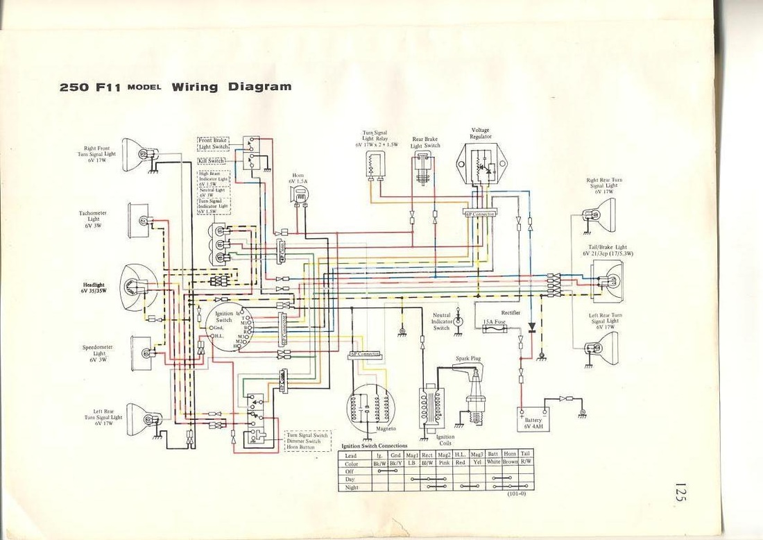
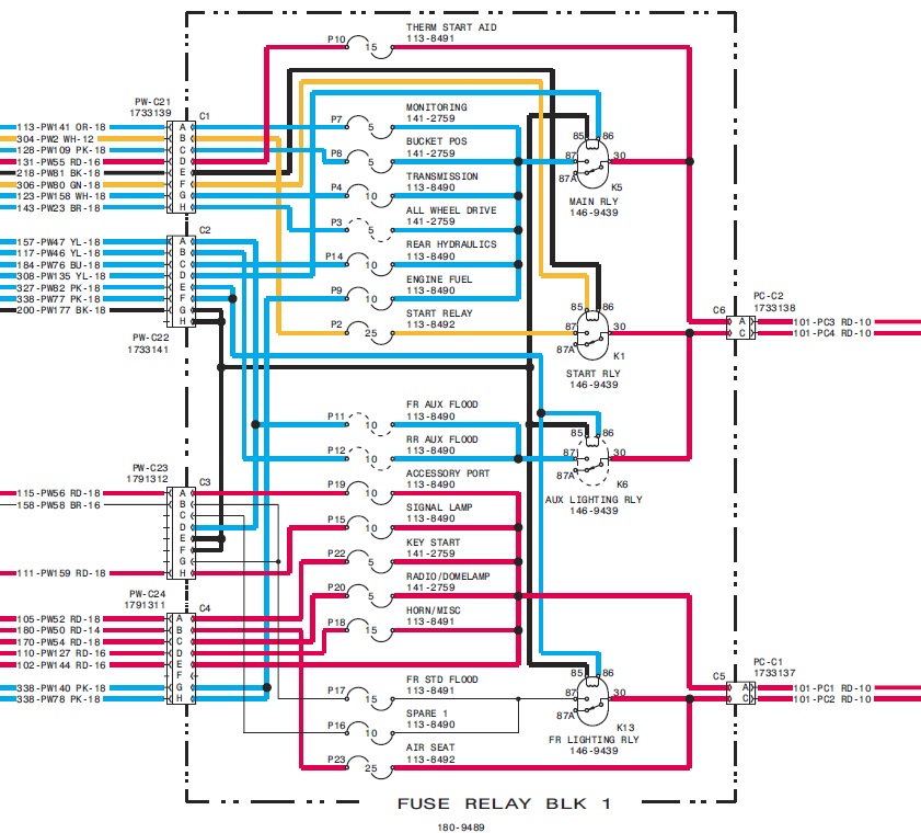
Freightliner M2 Wiring Diagram Download. Assortment of freightliner m2 wiring diagram. A wiring diagram is a streamlined conventional pictorial depiction of an electric circuit. It shows the elements of the circuit as simplified shapes, as well as the power as well as signal connections in between the devices.

2006 Freightliner Columbia Dash Blower Quit Tried Testing On Back Of Control Panel And No Power On Any Wires Changes
Description : 2001 Hzj79R Speedo Doesnt Work And Need Some Help With The Problem within Speedometer Wiring Diagram, image size 623 X 771 px. Description : Gps Speedometer Wiring Diagram Vdo Wiring Diagram Free Sample intended for Speedometer Wiring Diagram, image size 694 X 671 px. Description : Repair Sources And Write-Ups.
Subject: Re: freightliner speedometer ? central Ia. on ours there is one ground to the frame right next to the batteries, and one on the front by the starter. The one by the batteries has always been the issue for us have ground it off two or three times now and welded a new ground stud on. Next time im going to drill thru the frame an use a bolt.
New Freightliner Speedometer Wiring Diagram. By Rendra Posted on September 18, 2018. September 18, 2018. New Freightliner Speedometer Wiring Diagram -Welcome to help my blog, on this occasion I will teach you regarding freightliner speedometer […]
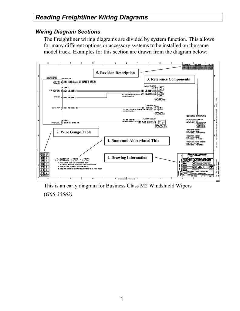
Speedometer issue has been going on app. 2 years. Reading Freightliner Wiring Diagrams. Wiring Diagram Sections The Freightliner wiring diagrams are divided by system function. This allows for many different options or accessory systems to be installed on the same model truck. Examples for this section are drawn from the diagram below: 5.
I have a 1998 freightliner FLD. the speedometer will. i have a 1998 freightliner FLD. the speedometer will occasionally quit working and then start working again while I am going down the road. ... do u have a wiring diagram for the temperature sensor on a freightliner fld ...

I Working On Fedex Truck As 98 Freightliner Mt45 And What Problem Is Speedmeter And Milages Not Working At All But It
3. Connect the speedometer wires as shown in the wiring sections. 4. Secure the speedometer to the dashboard using the provided bracket and hardware. Once the speedometer is mounted and wired into the vehicle, the speedometer should be tested to verify that the electrical connections are work-ing properly. First, watch the speedometer's ...
New Freightliner Speedometer Wiring Diagram In 2020 Freightliner Diagram Radio . Pin On Wiring . Pin On Electricalcars . 2005 Nissan An Wiring Diagram Wiring Diagram 175328 Amazing Wiring Diagram Collection . Loncin 110cc Wiring Diagram Kuwaitigenius Me Diagram Electronics Projects Diy Diy Electronics . Detroit Diesel Series 60 Ddec Iv Wiring ...
230v 2 Speed Motor Dpdt Switch Wiring Diagram; Cub Cadet Ltx 1045 Mower Deck Diagram; Scotts 1642h Deck Belt Diagram; Jvc Kd-r950bt Wiring Diagram; Freightliner Speedometer Wiring Diagram; Ddec V Ecm Wiring Diagram; Stihl 028 Diagram; Gotech Mfi X Wiring Diagram; Evcon Model No.brcq042c Capacitor Wiring Diagram; Beretta Px4 Storm Parts Diagram ...
Freightliner Speedometer Wiring Diagram - wiring diagram is a simplified okay pictorial representation of an electrical circuit. It shows the components of the circuit as simplified shapes, and the aptitude and signal links in the midst of the devices. A wiring diagram usually gives suggestion approximately the relative aim and treaty of ...
The speedometer does not work have change many parts to include Accelerator pedal, body control module, chassis control module, TCM, speed sensors, input and output sensors, no codes just don't have a wiring diagram for the instrument cluster to see which is the speedo wire or where it goes to. no one can seem to help me I have checked ...
The new information is that it is a SINGLE WIRE OUTPUT. He also confirmed that, unless there are other symptoms (like the Allison going bananas), the sensor itself is good. Freightliner wiring digram shows the "J2" connector from the TCM and shows pin 26 going to "transmission interface connector" in the wiring diagram.

Peterbilt Speedometer Wiring Diagram Trusted Wiring Diagrams In 2021 Peterbilt 379 Peterbilt Diagram
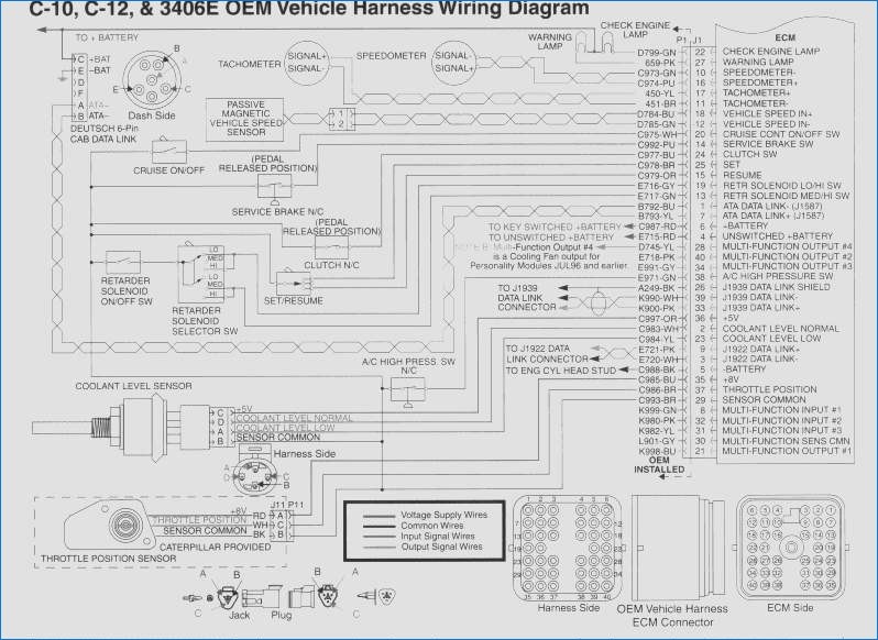
Freightliner Bus Coach Wiring Diagrams Service Manual Pdf Bus Coach Manuals Pdf Wiring Diagrams Fault Codes
Harley Speedometer Wiring Diagram Png And Harley Speedometer Wiring Diagram Transparent Clipart Free Download Cleanpng Kisspng
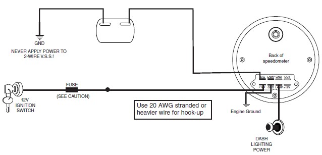
How To Install Auto Meter Programmable Speedometer Gauge 0 160 Mph Electrical Jeep Logo On Your 87 18 Jeep Wrangler Yj Tj Jk Jl Extremeterrain
Harley Speedometer Wiring Diagram Png And Harley Speedometer Wiring Diagram Transparent Clipart Free Download Cleanpng Kisspng
36 Isuzu Trucks Service Manuals Free Download Truck Manual Wiring Diagrams Fault Codes Pdf Free Download













Comments
Post a Comment