40 electronic mouse killer circuit diagram
Mar 5, 2018. So we live on a farm and have a problem with rats and mice in our barn. they need to go. we have tried several trap and no luck. I stumbled across some designs for electric shocking mouse traps. they look very simple. They used a pack to hold 4 "AA" batteries and a Voltage generator. I have attached a picture of the mouse trap I made. The electronic dog repellent circuit diagram below is a high output ultrasonic transmitter which is primarily intended to Electronic Mice Repellent Circuit P. Marian - 04/17/2008
Electronic Pest Repellent Circuit. There are many ultrasonic pest repellent devices available on the market but a major drawback is that their power output is low and their effectiveness suffers. This electronic pest repellent generates powerful ultrasonic signals to repel pests. In addition to the ultrasonic frequency oscillator built with the ...
Electronic mouse killer circuit diagram
Nov 29, 2021 · The schematics do not show placement or scale merely function and flow. ICs 5 pin can output oscillator signal which will drive VL1 to generate modulated infrared ray after the signal is amplified by V. Electronic Mouse Killer Circuit Diagram. Shop For Mouse Killer Now. They look very simple. Rat zapper ultra rzu001. did not want to copy his design. The circuit itself is a well-known electronic circuit freely available. Q: Will the circuit be damaged if I short-circuit the coins or Sp output? A: No, the output is protected by resistors to limit the current drain. Q: Will the NE555 component be damaged if I power it the first time with a faulty wiring? -- Assuming you're referring to a rat trap that uses electricity to kill --Yeah, I think you should start by building some boost converters that operated at safe voltages (e.g. a boost convert from 5V USB up to 12 or 24V), and get lots of experience with that.Then you'll maybe (not really) have enough experience to safely work with 8000V, and you'll be knowledgeable enough to understand the ...
Electronic mouse killer circuit diagram. Mosquito Repeller- This circuit produces a tone above the human audible range and this is supposed to keep the mosquitoes away. You need a piezo diaphragm that will respond to 15kHz and these are very difficult to find. __ 555-Timer. Mousetrap- All of a sudden there was a mouse under my roof and once also in my room. So I developed this ... Electronic Mouse Killer. IC's 5 pin can output oscillator signal, which will drive VL1 to generate modulated infrared ray after the signal is amplified by V. When there is no mouse, VD1 receives no infrared ray, and IC1 will oscillate automatically, making 8 pin output high level. VL2 is not illuminated and KN and high voltage circuit don't work. When there is mouse in the infrare ray detecting area, VD1 will receive the reflected infrared ray and turn 8 pin's high level into low level. Nov 04, 2020 · This electronic rat repellent circuit really is easy as it simply works with a several unique variations of components. Therefore to suit your needs who may be presently studying, researching electronics, may make an effort to practice causes this circuit as it is regarded as less difficult for newbies. Homemade rat trap from bottle. You will need a 2-liter soda bottle, barbwire, glue, toothpick and bait (peanut butter, bacon, sunflower seeds). Before making the rat trap diy, put on latex or vynil gloves to avoid leaving human scent. Take a 2-liter soda bottle and cut 2 inches off the top.
Select of interesting electronic circuits that require only a single transistor ideal for education: Misc: Feb 20, 2010: 0: Small selection of useful circuits: Misc: Feb 09, 2010-2: Variety of simple motor control circuit diagrams using SCR or TRIAC: Control: Feb 20, 2010-1: Super mixer with microphone input / amplifier including a PCB layout ... NITA. 270 MINI ELECTRONICS PROJECT WITH CIRCUIT. D IAGRAM. This Book is writ ten for all the people who love innovation. It is the big collection of ideas to do. some innovative project, to make ... After we present a circuit of electronic mosquito repellent, this time will be continued with a circuit of electronics that are not less interesting, that is electronic rat repellent circuit.. Actually the working principles of electronic mosquito repellent and mice repellent are exactly same, using echolocation disliked by both the animal. Squirrel Zapper Circuit Diagram. circuit diagram and PCB design of electric zapper for rodent control I Will it also 'ZAP' the grey squirrels who ate most of my broad beans. Disclaimer: This circuit is very similar to the one used in Don's Components have been provided for both the zapper function and the succor.
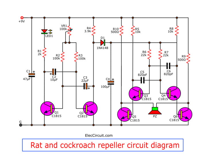
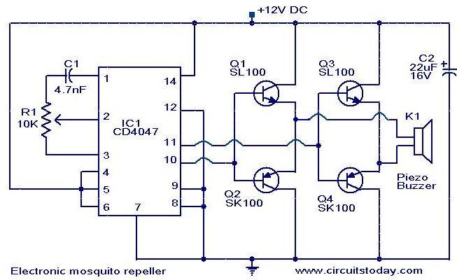
Squirrel Zapper Circuit Diagram. That's how a zapper works. I'll be wiring so that when the squirrel climbs the metal pole and touches The grid he will complete the circuit. Disclaimer: This circuit is very similar to the one used in Don's Components have been provided for both the zapper function and the succor. Description. Here is the circuit diagram of an ultrasonic mosquito repeller.The circuit is based on the theory that insects like mosquito can be repelled by using sound frequencies in the ultrasonic (above 20KHz) range.The circuit is nothing but a PLL IC CMOS 4047 wired as an oscillator working at 22KHz.A complementary symmetry amplifier consisting of This is my homemade rat zapper that I was forced to make a while back because I had a problem with 2 rats that found their way into our home, chewed up expen... Figure 1 Rat and cockroach repeller circuit diagram. LED will is used for power on display of this project. And VR-100K will be adjustable of timing range. The low frequency will be sent to control the high frequency generator. Which consist of TR3 and TR4 and R5-R8, C5, C6 will be combine to increasing frequency rises up.
pets control - Household Supplies Prices and Promotions ...
Anyway, the electronic rat traps work, and the rat doesn't get a chance to snack on the bait. I've been using pepperoni dog treats, only had to replace twice. The first one I bought was under $30 at Home Depot. Went back a month later, $39.95. The second one hasn't kill a rat, but the bait remains.

Electronic Mice Repellent Circuit
than 1500 electronic mouse killer circuit diagram at pleasant prices up to 27 ... Ultrasonic Pest Repeller Reject Control Electronic Repellent Mouse Rodent .... by KN Kailas · Cited by 1 — Abstract:-The common method of pest control is the use of the pesticides. ...

Low Cost Electronic Rat Repellent | Electronic Schematic Diagram
Electronic Diagrams & Schematics 6 Examples of Electronic Schematic Diagrams Electronic schematics use symbols for each component found in an electrical circuit, no matter how small. The schematics do not show placement or scale, merely function and flow. From this, the actual workings of a piece of electronic equipment can be determined.
DC circuit for rat killer | Electronics Forum (Circuits ...
Circuit Diagram (wired operation) 24 gauge solid phone wire (preferred) +-NO COM Terminal strip inside GSM controller box + NO COM 1 1 2 2 7 _ 7 12 Volt DC 12 Volt DC The GSM controller draws 40ma during standby operation Notes - The D1 diode will prevent excessive arcing at the switch contacts inside the Auto Relay.
Easy Digital Password Door Lock Circuit Diagram
Feb 04, 2017 · Alibaba com offers 48 mosquito killer circuit diagram products About 66% of these are pest control, 33% are bug zappers, and 14% are pool lights .... Jan 22, 2020 — This critter repellent is basically a high frequency emitter ( 61 Khz ) based on the 555 timer . ...

Simple Rat Repellent Circuit
Ultrasonic Pest Repellent Circuit. The explained Ultrasonic Pest repeller is a device that generates ultrasound or a very high frequency noise in the range of over 20 kHz which becomes useful for repelling or scaring away animals like stray dogs, cats, mice bats, etc. This becomes possible since these animals are able to easily detect the ...

Ultrasonic Rat Repellent
Sep 28, 2013. #4. THE_RB said: Possibly the best way to get rid of mice and rats is to remove their food source, they eat a lot of calories so they only breed and thrive when there is a food source. Things like open bags of chook food, dry dog food, grains, open trash containers are what attracts the rats and allows them to breed up.

How to make a mouse electric shock Trap & Circuit Diagram ...
Electronic Mouse Killer Circuit Diagram - Free Wiring Diagram best jalishamav.blogspot.com. The concepts of electronic mosquito repellers are simple and we can build a simple mosquito repellent circuit at home easily by using 555 timer ic and few other commonly available components.
Mouse and Rat repellent circuit using astable multivibrator
-- Assuming you're referring to a rat trap that uses electricity to kill --Yeah, I think you should start by building some boost converters that operated at safe voltages (e.g. a boost convert from 5V USB up to 12 or 24V), and get lots of experience with that.Then you'll maybe (not really) have enough experience to safely work with 8000V, and you'll be knowledgeable enough to understand the ...

Buy Mouse Traps,Electronic Mouse Trap,Rat Trap for 100 ...
did not want to copy his design. The circuit itself is a well-known electronic circuit freely available. Q: Will the circuit be damaged if I short-circuit the coins or Sp output? A: No, the output is protected by resistors to limit the current drain. Q: Will the NE555 component be damaged if I power it the first time with a faulty wiring?

Electronic Mouse Trap
Nov 29, 2021 · The schematics do not show placement or scale merely function and flow. ICs 5 pin can output oscillator signal which will drive VL1 to generate modulated infrared ray after the signal is amplified by V. Electronic Mouse Killer Circuit Diagram. Shop For Mouse Killer Now. They look very simple. Rat zapper ultra rzu001.
Download Electronic Rat Trap Circuit - Full Size Png Image ...
Electronic Live Capture Mousetrap

Cat and Dog Repeller
Todays Circuits ~ Engineering Projects | : Electronic ...
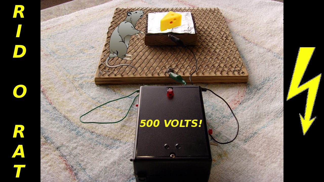
RID-O-RAT Homemade Electronic Pest Control Device

Rat and cockroach repeller circuit by Apichet Karipum

Electronic Mouse Trap

Electronic Mosquito Repellent Circuit | Engineers Gallery

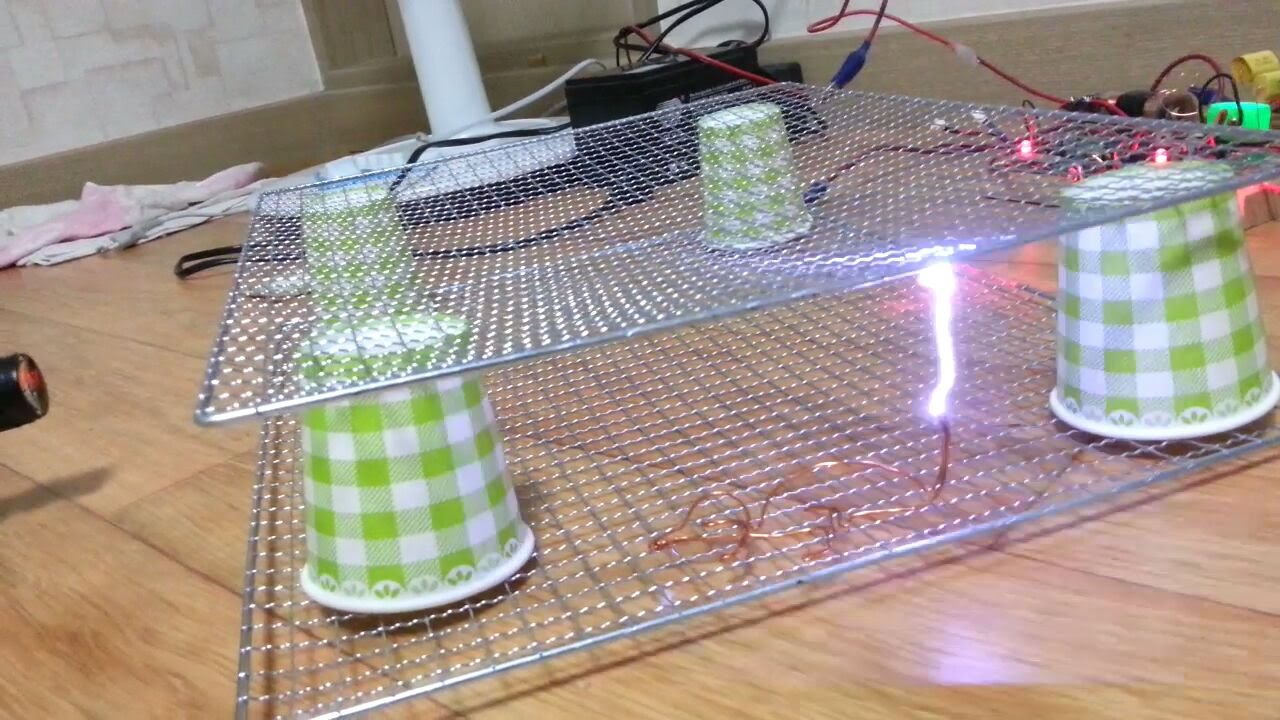
High Electric Trap Mouse at Home Easy Make with small transformer

how to make electric mouse rat trap / high voltage | Simple Inventions | Homemade DIY Ideas
![Mouse Trap [2020]](https://i.ytimg.com/vi/X1SlSHW1r0E/maxresdefault.jpg)
Mouse Trap [2020]
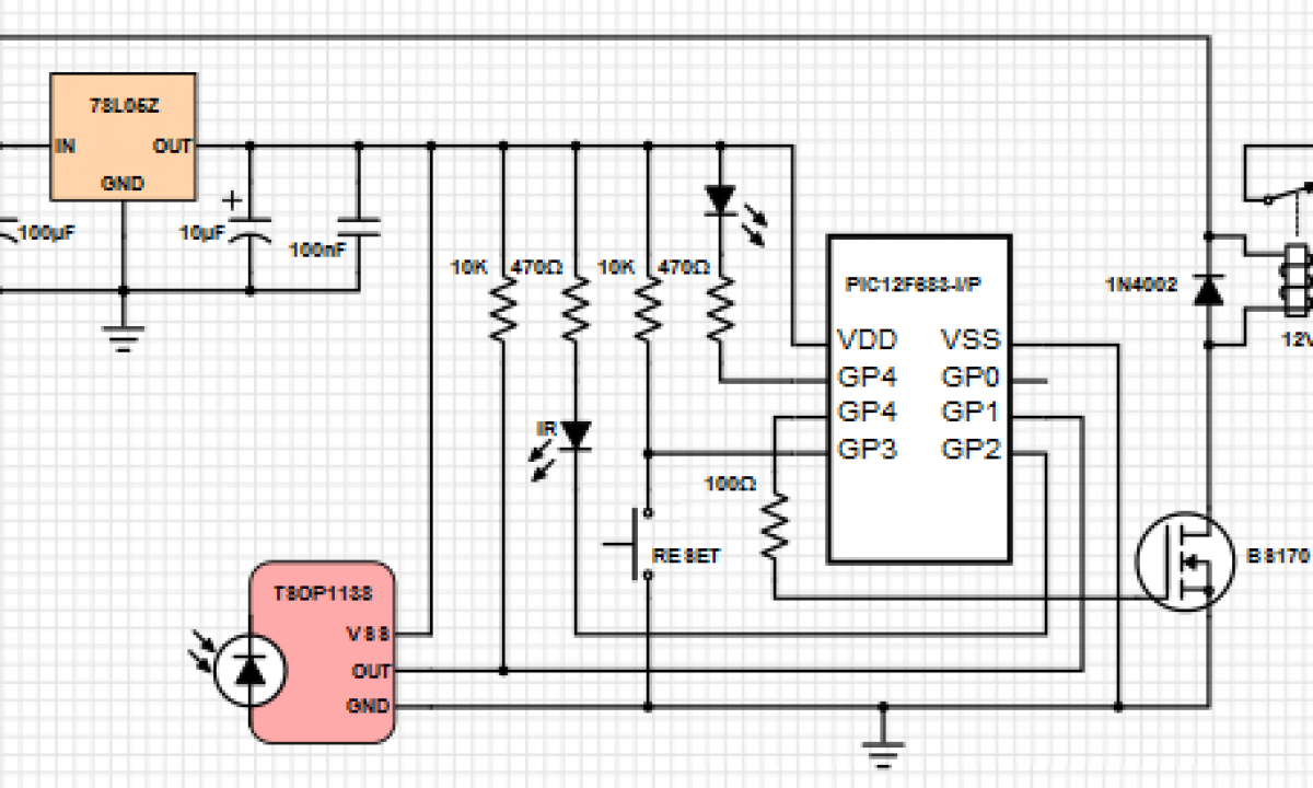
Electronic Live Capture Mousetrap - Raspberry PI Projects

Insects and mouse repellent circuit using IC556

Ultrasonic Pest Repellers

Electronic Mouse Trap - Album on Imgur
Basic MOUSETRAP pipeline without logic processing. | Download ...
Electric Mouse Trap - Making - TheWikiHow

Mouse-O-Leum (Multiple Live Catch) Mouse Trap - Hackster.io
1st Rat Trap | Nghia Ho
Research Article Special Issue

Arduino Mouse Trap : 5 Steps (with Pictures) - Instructables

electronic mouse trap circuit - Basic_Circuit - Circuit ...
An IoT Smart Rodent Bait Station System Utilizing Computer Vision

Ultrasonic Pest Repellers
Frontiers | Unbiased Sampling for Rodents and Other Small ...

DIY Mini Drone: Arduinoâ„¢ Altitude Control | STEM Activity

ELECTRONICS IDEA: Mouse and insects repellent circuit using IC556

Electronic Mosquito Repellent Periodically 'ON' and 'OFF' by ...

Where can I find circuit for electronic rat trap?


Comments
Post a Comment