43 ddec 2 wiring diagram
a DDEC II to DDEC IV conversion is made on a vehicle using the DDEC II cruise control feature. Figure 3 Typical DDEC II Cruise Control Wiring Schematic Remove the wire identified as DDEC circuit #542 from the Set/Coast Switch. At a convenient point, splice circuit #542 into the cruise control switched ground circuit. 9 Jul 2020 — Looking for wiring diagram for ddec 2 Detroit that shows power to ecm just need wiring diagram - Answered by a verified Technician.1 answer · Hello and thank you for using Just Answer. My name is ***** ***** I'd like to try and help. ...
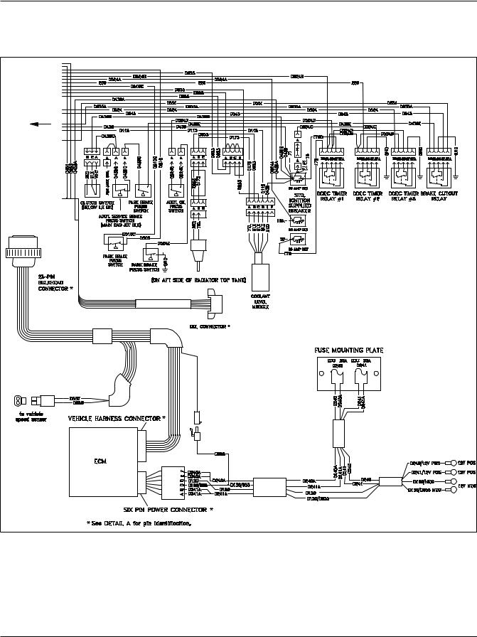
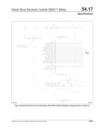
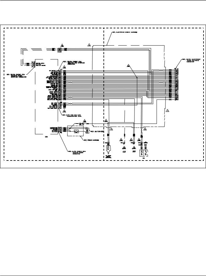
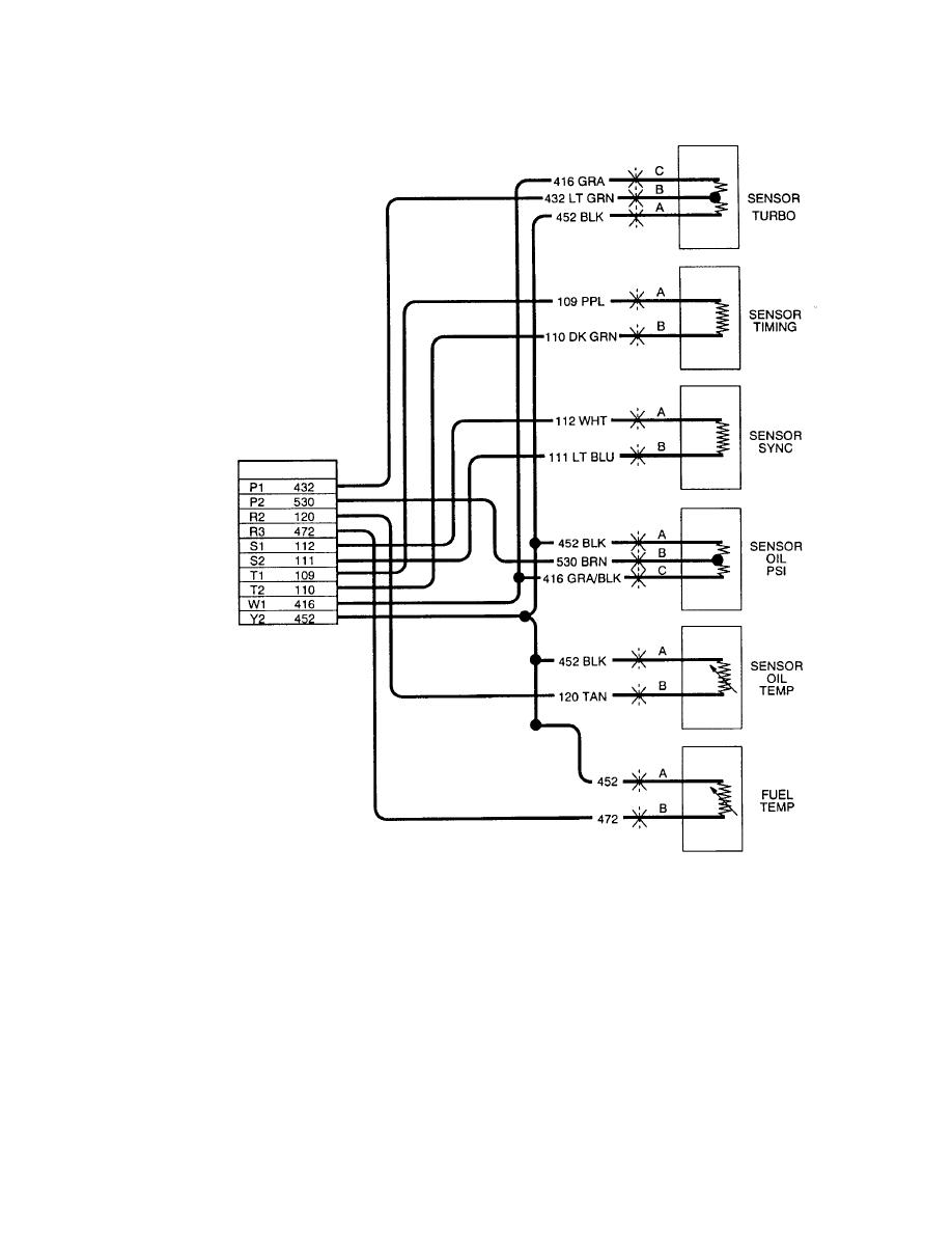
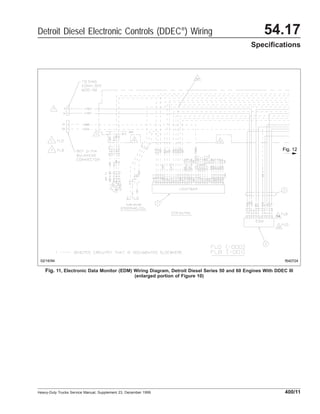
See Fig. 1 for a full view of the Detroit Diesel Electronic Controls (DDEC) II wiring diagram. See Fig. 2 and Fig. 3 for partial (detailed) views of the full view of the DDEC II wiring diagram. See Fig. 4 for a full view of the DDEC III wiring diagram (the engine side). See Fig. 5 and Fig. 6 for partial (detailed) views of the full view of the DDEC III wiring diagram (the engine side).
Ddec 2 wiring diagram
Wiring Schematics Manual contains detailed electrical wiring information, especially for Peterbilt DDEC II Engine. Electronic instruction contains diagrams for hydraulic and electronic systems and is intended for quality service and the prevention of malfunctions. One thing missing on the schematic is jake brake wiring. It only shows the ecm wire 508 and how it actuates the jake brake relay. I see the ddec 2 system used a ecm for jake brake control of high med and low. I also saw somewhere that they also used a relay set up and I could not find a schematic for that anywhere. HARDWARE AND WIRING DDEC V supports three independent data links. There are two links on the Vehicle Interface Harness (VIH). One link is based on SAE J1708, and the second is SAE J1939. The other link, on the Engine Harness, is CAN based and will be used for proprietary communications such as
Ddec 2 wiring diagram. Specifically the 2nd drawing is DDEC 2. Note there is not a line item EGR Valve. The 1st is a wiring diagram dash to sensors, or sensors to dash lights. However you want to look at it. Unless you can point out the actual location of the VPODS to ECM. 21-December 16 Hi, i need all wiring diagram and all foult Code list pdf EPA 07 to EPA 13 all DDEC VI Series 60, DD13, DD15 and DD16 View troubleshooting information, wiring diagrams, and step-by-step troubleshooting procedures for a 2 DDEC II Detroit Diesel Series 60 engines equipped with DDEC II electronic control systems are identified by a "U" in the sixth position of the model number. Example: 6067GU60. Detroit Diesel Electronic Controlled Series 60 engines can be equipped with a variety of options designed to warn the operator of an engine malfunction. Depending upon application, some units Schematic Diagram of DDEC II. The DDEC II ECM is packaged in a . If ATEC is used, connect this wire to ATEC ECM. Wire Cut off black wire and insulate end. For Model DDEC II (2-mode), use the wiring diagram for. 3 for partial (detailed) views of the full view of the DDEC II wiring diagram. See Fig.
DDEC 2 ECM- Wiring Diagram - MHH AUTO - Page 1. Latest News: Creating SIS USER for SIS offline Volvo PTT 2.7.116 Truck automátic software Xzent Navisoft for x-402,422,f-220 With Europe+Turkey 2021.Q2 Map SpeedCam Included RMC Solution - Activate and update maps - 2021 (remotely) looking full backup 508 dcm6.2a 2.0 hdi 180 cv PIWIS III screen ... The DDEC II was horrible on the diagrams they provided for it. It wasn't until DDEC III/IV that there was a real diagram. I do have the DDECC II diagram for the Peterbilt, which used the same wire numbers in the Volvo if that will help you. It is the same as the Detroit one, just ahs a Peterbilt logo on it. Kenworth DDEC II R115 Wiring Schematics Manual PDF. This manual includes schematics, step by step instructions, wiring diagrams, serve information for Kenworth DDEC II R115. Program has a very comfortable and pleasant interface, it is designed to run on a PC. Manual supports English and comes in PDF format. 2 JAKE BRAKE® TROUBLESHOOTING: DDEC II CONTROLS JAKE BRAKE® MODELS 71/92A WIRING DIAGRAM DDEC SERIES II (2 MODE) CONTROL GROUP P/N 017363 +12V RED GREEN ORANGE GRN/YEL PURPLE GRAY CONNECT GROUND TO NEGATIVE BATTERY POST OR ENGINE FRAME RAIL INSULATE END OF ORANGE WIRE Purple and gray wires may be used by some vehicle manufacturers. If not ...
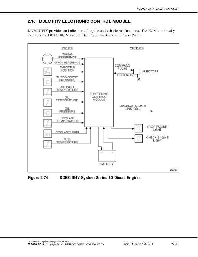
DDEC V WIRING DIAGRAM PIN NO. WIRE COLOR DESCRIPTION PIN NO 1 COLOR WHT DESCRIPTION INJ COMMON 1,2,3 GROMMET ASSEMBLY DDC. Diagrama De Cabina Oem Ddec V 10 3 Vi Wiring Diagram 5 Wikiduh Com With 4 Ecm. 14 ddec 4 ecm wiring diagram car cable and detroit diesel series 60 best. DDEC V provides an indication of engine and vehicle malfunctions. 3.2.2 ECM PART NUMBERS Part numbers for DDEC III and IV ECMs are listed in Table 3-3. Part Number Description Voltage No. of Cylinders 23518645* DDEC III - Standard On-highway ECM 12/24 V 6 23518743 DDEC III - Universal ECM 12/24 V 8 23518744 DDEC III - Series 4000 ECM only 24 V 8 23519307 DDEC IV - Standard On-highway ECM 12 V 6 This ddec ecm iii wiring diagram fiat dan wiring schematic has x pixel and can be found at schematron.org Series DDEC III/IV SINGLE ECM TROUBLESHOOTING GUIDE The following wire schematics support the communication harness; see Figure Figure See Fig.1 for a full view of the Detroit Diesel Elec- tronic Controls (DDEC) II wiring diagram. 10/09/98 f540679 WATER LEVEL PROBE Fig. 2 Fig. 3, DDEC II Wiring Diagram (enlarged portion of Figure 1) Detroit Diesel Electronic Controls (DDEC®) Wiring 54.17 Specifications Heavy-Duty Trucks Service Manual, Supplement 23, December 1999 400/3
Fig. 2, DDEC II Wiring Diagram (enlarged portion of Figure 1) 400/2. Heavy-Duty Trucks Service Manual, Supplement 23, December 1999 Detroit Diesel Electronic Controls (DDEC) Wiring. 54.17 Specications. Fig. 2. WATER LEVEL PROBE. 10/09/98. f540679. Fig. 3, DDEC II Wiring Diagram (enlarged portion of Figure 1)
Through the thousand pictures on the web in relation to detroit 60 series engine diagram, picks the top series having best resolution just for you, and now this pictures is usually one among photographs choices in our best graphics gallery concerning Detroit 60 Series Engine Diagram.I'm hoping you may enjoy it. This impression (Ddec Ii Wiring Diagram Ddec 2 Ecm • Ohiorising for Detroit 60 ...
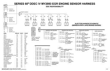
Detroit Diesel DDC-DDEC II Wiring Diagram.pdf: 66.4kb: Download: Detroit Diesel DDEC II and III Wiring Diagrams.pdf: 993.1kb: Download: Detroit Diesel DDEC III-IV Series 60 Injector Harness Schematic Wiring diagram.png: 350.1kb: Download: Detroit Diesel DDEC IV Series 60 MY2003 EGR engine sensor harness Wiring Diagram.png: 308.7kb: Download
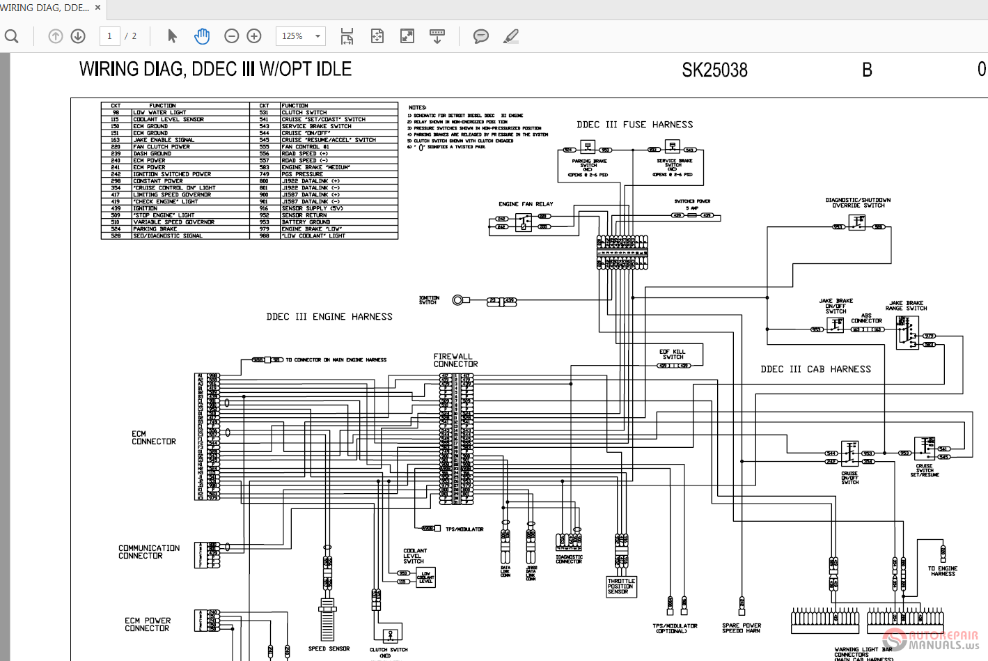
WIRING, CAB HARNESS DDEC II. 1. B. SK19918. LOCATE BEHIND "B" PANEL. TIE BACK BUT LEAVE ACCESSIBLE. CONNECT TO 2-WAY START/KEY HARNESS SEE SK18869 FOR WIRING 150. 115. DATA LINK AND CAP.
92.2 INJECTOR HARNESS WIRING SCHEMATIC - SERIES 60 ENGINES 92.2 INJECTOR HARNESS WIRING SCHEMATIC - SERIES 60 ENGINES ... DDEC CAVITY -2) WIRE 562 561 ENGINE CONN. 24622 All information subiect to change without notice. ENG BRAKE LOW CTL ENG BRAKE MED CTL For "Go To A", see Figure 92-9.
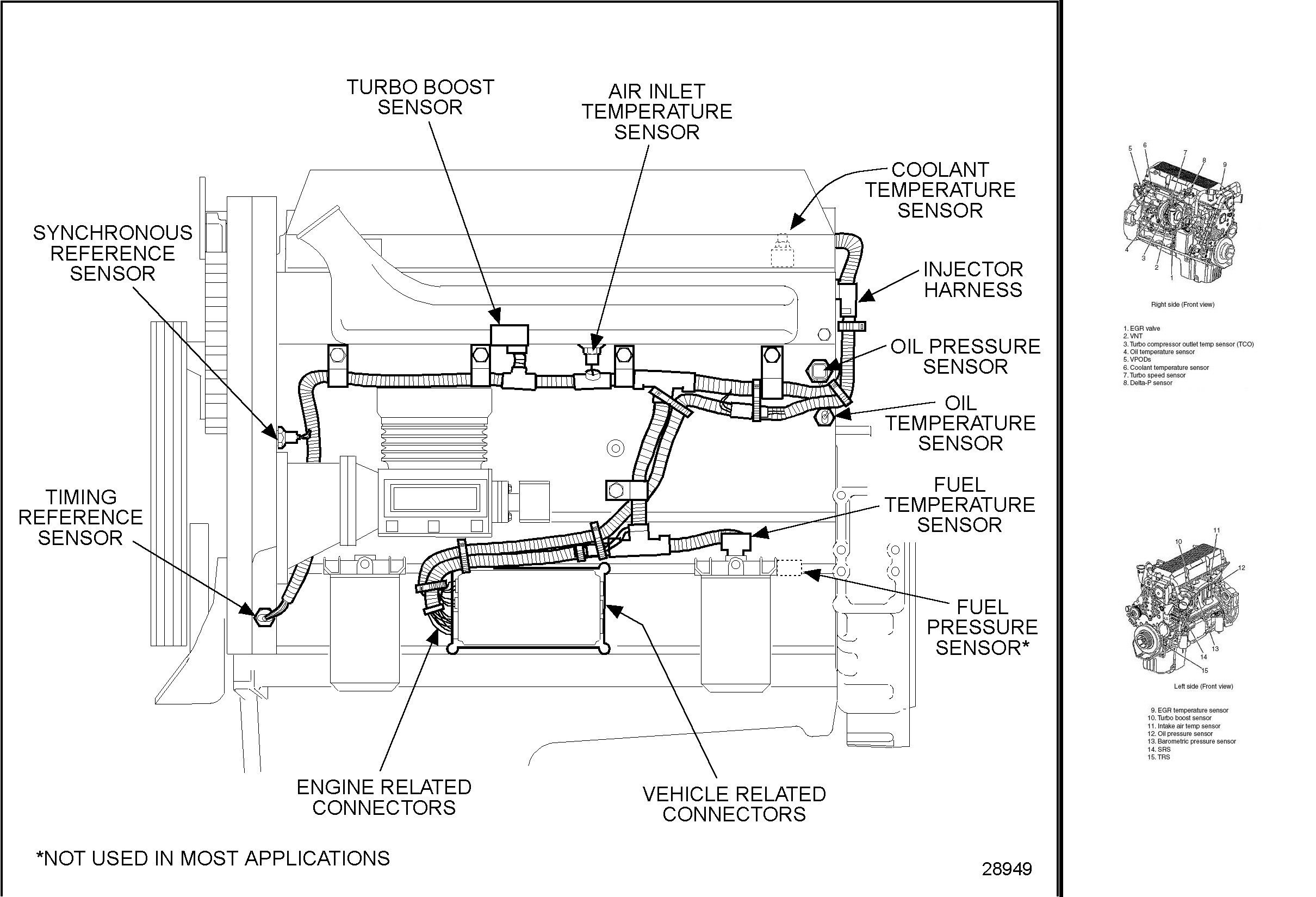
Source. detroit diesel series 60 ecm wiring diagram inspiration ddec iii iv kenworth t wiring diagram detroit.The Detroit Diesel Series 60 DDEC III, IV, V, VI Wiring Diagrams are also known as Electrical Schematics or Circuit Diagrams. The wiring diagrams cover both the Series 60 engine harness and Series 60 vehicle interface harness.
DDEC IV APPLICATION AND INSTALLATION MANUAL DDEC IV APPLICATION AND INSTALLATION MANUAL ABSTRACT Detroit Diesel Corporation has produced electronically controlled engines for nearly two decades.
The wiring diagrams cover both the Series 60 engine harness and Series 60 vehicle interface harness. List of files in the Detroit Series 60 Wiring Diagram. DDEC I, DDEC II, and DDEC III & IV Schematics. DDEC I controls the timing and amount of fuel injected into each cylinder. The system also monitors several engine functions using various ...
ddec ii cab harness main cab harness d stop engine check cruise control e data link conn 901 900 f1 f2 524 524 68 68 419 a150 a150 439 439 g h 7 sk20627 a mcd dph 08-30-89 89057-03 rg ms replaced cb's w/15a fuses roc b-7 c ndp ndp 04-04-90 36548-02 ms a-5 revised jake instl rg roc d jjx mnh 09-04-90 rg 35989-08 ms
Ddec Ii And Iii Wiring Diagrams Pdf Txt. Ddec ii iv wiring diagram 1 vehicle harness schematic detroit sel and iii engine service manuals diagrama motor v pdf docer com ar de vi 2 doent mcm electronico diagrams txt electronic itemanuals advanced control internal brake for system ecm modulo mercadolibre with jake need help from atec integration guru 3 y 4 i have a series 60 my injector ...
Detroit Diesel The history of this family of diesel engines began even before World War II, when the 71-series 6-cylinder in-line diesel engine was introduced as the flagship product of the Detroit General Motors diesel engine division. Then, in 1957, a wider version appeared. Interestingly, the 71 series designation refers to the cubic capacity of one cylinder, measured in cubic inches.
HARDWARE AND WIRING DDEC V supports three independent data links. There are two links on the Vehicle Interface Harness (VIH). One link is based on SAE J1708, and the second is SAE J1939. The other link, on the Engine Harness, is CAN based and will be used for proprietary communications such as
One thing missing on the schematic is jake brake wiring. It only shows the ecm wire 508 and how it actuates the jake brake relay. I see the ddec 2 system used a ecm for jake brake control of high med and low. I also saw somewhere that they also used a relay set up and I could not find a schematic for that anywhere.
Wiring Schematics Manual contains detailed electrical wiring information, especially for Peterbilt DDEC II Engine. Electronic instruction contains diagrams for hydraulic and electronic systems and is intended for quality service and the prevention of malfunctions.

![Wirning Harness DDEC - [PDF Document]](https://reader021.docslide.net/reader021/html5/20170913/55cf9d88550346d033ae0800/bg4.png)





![Ddec Ii And Iii Wiring Diagrams [PDF|TXT]](https://html.pdfcookie.com/02/2020/01/15/68v4qggydx2g/bg3.jpg)



![Wirning Harness DDEC - [PDF Document]](https://reader021.docslide.net/reader021/html5/20170913/55cf9d88550346d033ae0800/bg3.png)




![Ddec Ii And Iii Wiring Diagrams [PDF|TXT]](https://html.pdfcookie.com/02/2020/01/15/68v4qggydx2g/bg1.jpg)

![Ddec Ii And Iii Wiring Diagrams [PDF|TXT]](https://pdfcookie.com/img/crop/300x300/1g2w6xjonzl5.jpg)


![DDC-DDEC Wiring Dagram - [PDF Document]](https://demo.fdocuments.in/img/378x509/reader024/reader/2021010105/54511835af7959d40d8b4712/r-2.jpg)


Comments
Post a Comment