42 0 10 volt dimming wiring diagram
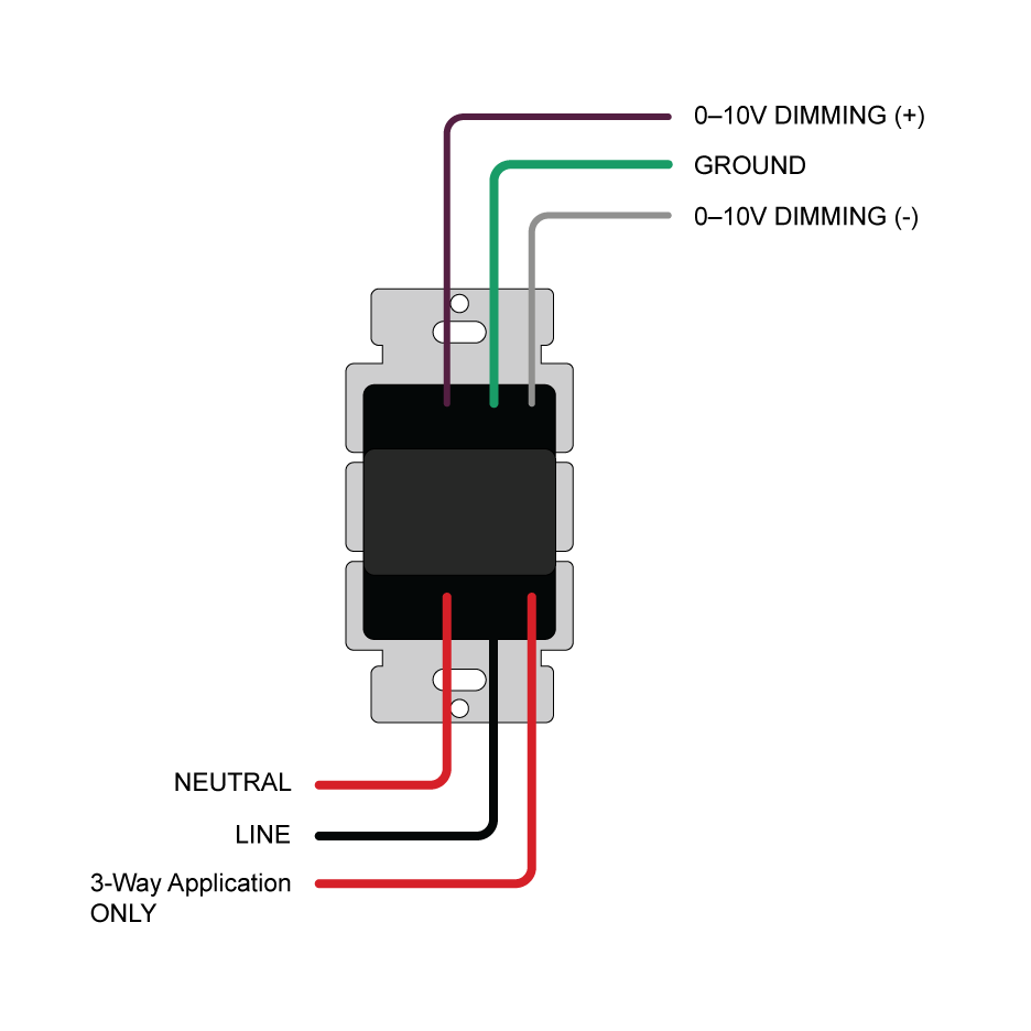
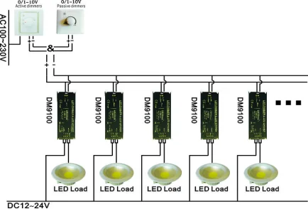
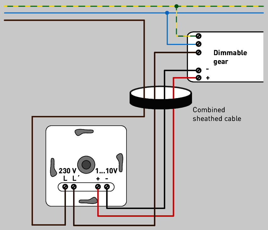
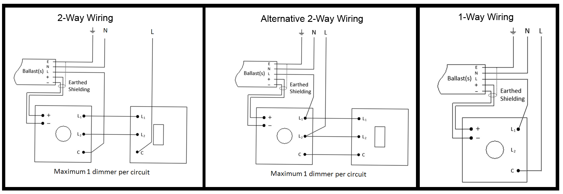
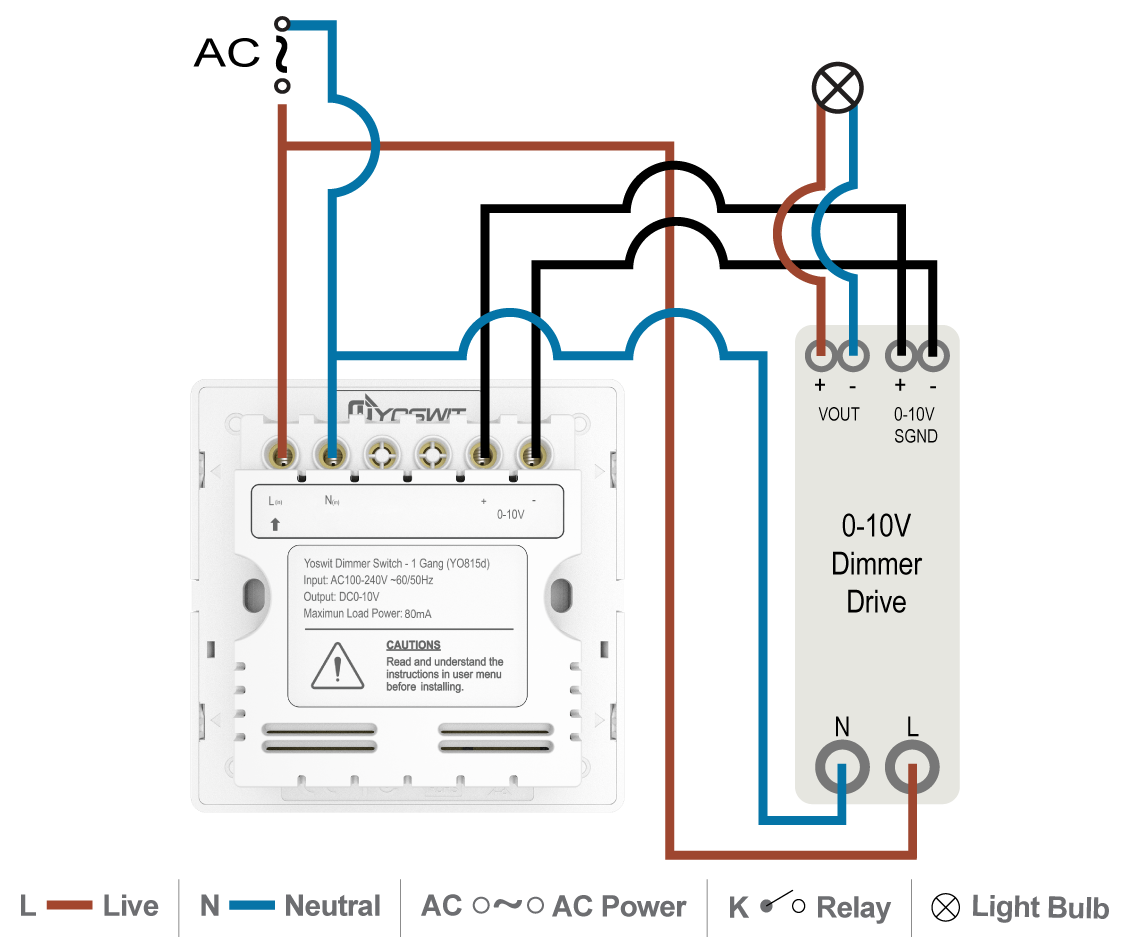
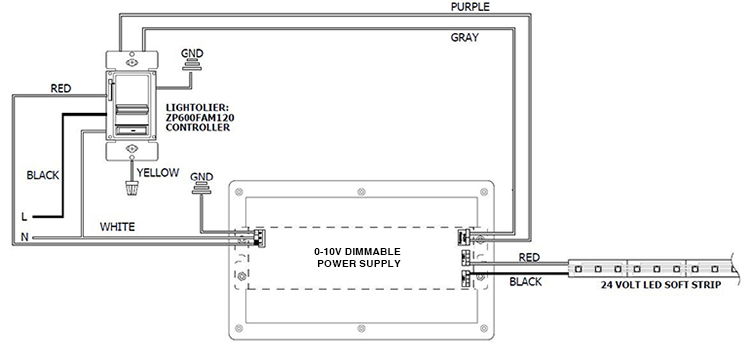
Lutron 0 10v Dimmer Wiring Diagram 0- advance mark vii v electronic dimming ballasts lutron® eco® 10 volt option wire controls according to the appropriate wiring diagram shown in.v preset dimmer for use with: volt lighting control devices package contents and parts identification (figure a) operation the volt low-voltage lighting control provides dimming control for volt … Low Voltage LED 0-10V Dimming | USAI At 0 Volts the device will dim to the minimum light level allowed by the dimming driver, and at 10 Volts the device will be operating at 100%. A 0-10V dimmer is considered analog dimming, and all USAI 0-10V dimming options are considered to be "sink" type dimming. A typical 0-10V wiring diagram is shown below: 0-10V Dimming
0-10 Volt Dimming Wiring Diagram 0-10 Volt Dimming Wiring Diagram 03.01.2019 2 Comments In dynamic lighting control applications, "" describes the use of an analog A dimmable LED driver includes a power supply circuit that produces. A V dimmer is considered analog dimming, and all USAI V dimming options are considered to be "sink" type dimming. A typical V wiring diagram is.
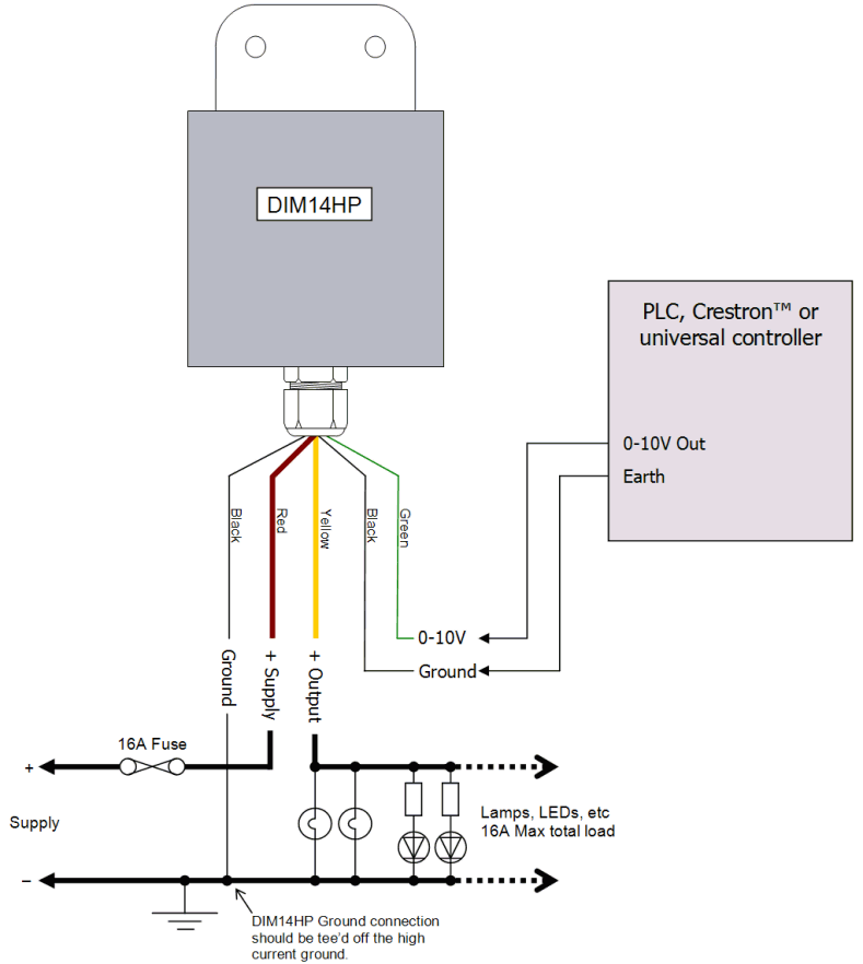
0 10 volt dimming wiring diagram
Understanding 0-10V Dimming with Today's LED Commercial ... 0-10V dimming is a lighting control method that - on direct current voltage (DC) between 0 and 10 volts - can produce light at varying intensity levels. 0-10V dimming is the simplest control system for lighting, providing smooth operation and dimming down to 10%, 1%, and even 0.1% light level. At 10 volts, the light will go to maximum power. 0-10V Wire Colors to Change 0-10V dimming wires, the wires used to communicate dimming intensity via a 10-volt signal, can be easily identified on wiring diagrams, installation instructions, and dimmable drivers by their colors: gray and violet (although violet is often referred to as purple). This will soon change, however, as new codes and guidelines take effect. PDF 0 10 Volt Dimming Wiring Diagrams 0 10 Volt Dimming Wiring Diagrams 0 10 Dimming Ballast Wiring Diagram Pdf E books April 5th, 2019 - Ebook 0 10 Dimming Ballast Wiring Diagram currently available at kidsintow co uk for review only if you need complete ebook 0 10 Dimming Ballast Wiring Diagram please fill out registration form to access in our databases
0 10 volt dimming wiring diagram. 0-10 volt or 1-10 volt dimming - Electrician Talk (one cable is a 3 wire)Ground Hot Neutral 100-277v power (the other cable is a 2 wire) for dimming Purple Represents + 10 volts and a gray wire representing the signal. I don't have any paper work on these fixtures but they are the newer style fixtures that utilize 1 to 10 volts for dimming as apposed to 0 to 10 v PDF Provolt™ 0-10V Dimming Room Controllers (PRC) Class 2 0-10V Wiring 18 gauge stranded recommended, 0-10V sinking 50mA max Class 2 Low Voltage Wiring 18 gauge stranded recommended, maximum wiring: 500 feet total system, 0-28VDC, 2mA-50mA General Daylighting Zones Single and dual zone daylighting available Dimming Area Control Single area control (keypad simultaneously controls primary and ... 0-10 Volt Dimming Wiring Diagram | Dmx, Arduino, Led lights Perfect 1 10v Dimming Wiring Diagram Image Collection Electrical. 0 10 Volt Dimming Wiring Diagram Best Lighting Dmx Dimmer System. 0 10 Volt Dimming Wiring Diagram Inspirational Wiring Diagram Light L Levi Elektronika 320 followers More information Find this Pin and more on Arduino Example by Levi Elektronika. Low Voltage Outdoor Lighting 0 10 Volt Dimming Wiring Diagram | Wiring Diagram - 0 10 ... 0 10V Dimming Wiring Diagram Led Downlight - Wiring Diagrams - 0 10 Volt Dimming Wiring Diagram Wiring Diagram consists of numerous in depth illustrations that present the link of assorted items. It includes directions and diagrams for various types of wiring methods and other items like lights, windows, and so forth.
PDF 0-10V dimming wiring diagram - Crenshaw Lighting 0-10V dimming wiring diagram 0-10V dimmer switch Leviton IP710-LFZ or equal For other types of dimming control systems, consult controls manufacturer for wiring instructions switched hot (black) switched hot (red typical) low voltage dimming wires (purple & gray typical) + Electrical Panel hot (black typical) 120V or 277V, 60 Hz 0-10V 3 Way Dimmer Switch Wiring Diagram - Database ... Following diagrams is fairly simple, but making use of it inside the scope of how the device operates is a new different matter. The best advice is not necessarily only look from the diagram, yet understand how the components operate when in use. 0-10V 3 Way Dimmer Switch Wiring Diagram Source: PDF Single Pole (One location) or 3-Way (Multi-location) 0-10V ... Wiring Diagram 1 Insulating Label Green Ground Black White Red Hot (Black) Neutral (white) Line 120/277VAC 60Hz Dimmer) Gray (-) Yellow To Lamps Red Blue 0-10 VDC Ballast Yellow/ Red 1 3 7 Matching Remote Additional Neutral Wire 2 Dimmer 2 3 4 Red Violet White Yellow/Red Gray Black Green 6 5 1 Wiring Diagram 2 Green Ground Green Ground White ... Dimming High Lumens LED 0-10v - LED Light Expert A: Zero to ten volt (stylized as 0-10v) is actually one of the earliest signaling system invented for lighting control and is also one of the simplest: it uses a control signal of low voltage that ranges from 0 to up to a maximum 10 volts. The amount of volts sent to the LED driver, tells it how bright to be. Send 0 volts and the light is off. Send 10 volts and the light will go to maximum power.
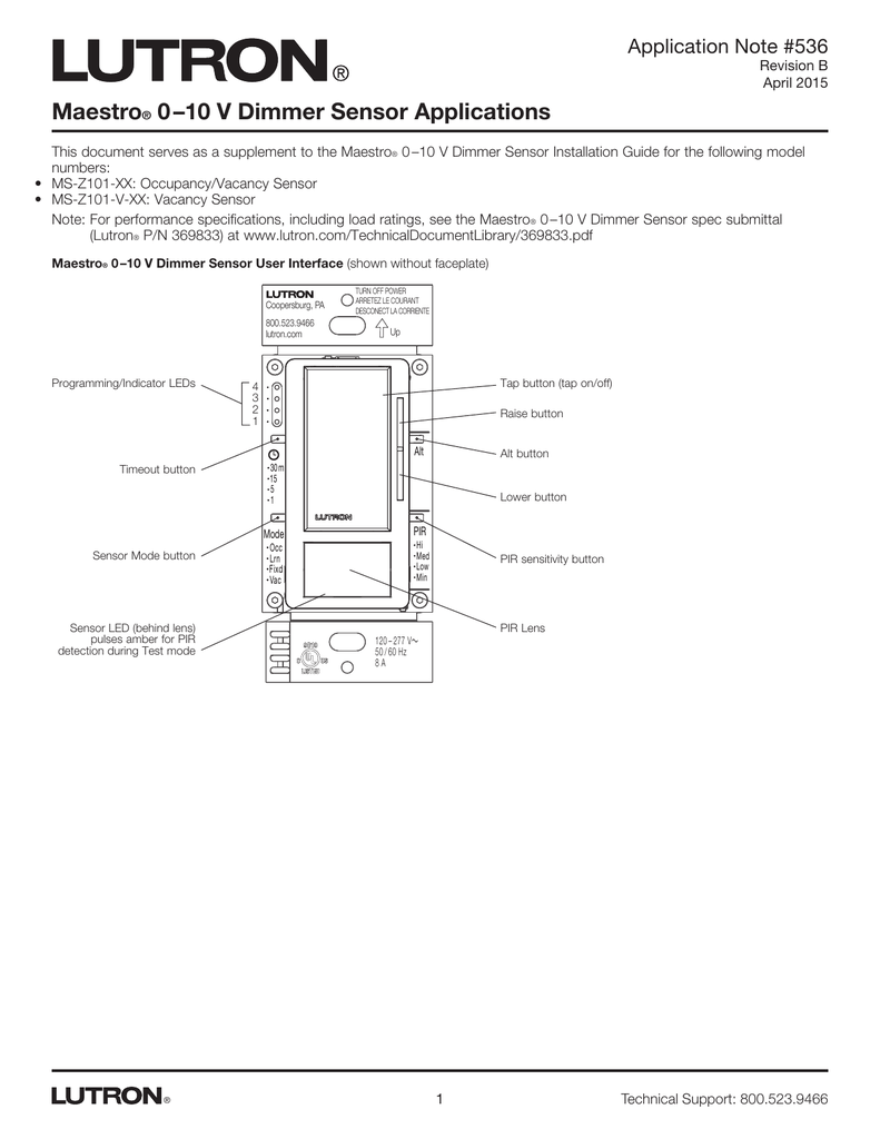
PDF 0-10v Dimmer Wiring Diagram - LTF Technology - Always follow local electrical code regulations when installing LED drivers & fixtures. - DO NOT attach 0-10V dimming wires to hot / line voltage wire. - Leave wire caps on 0-10V dimming wires when not in use to prevent short circuit. - For LTF UniDriver power supplies, DO NOT install / use ELV and 0-10V dimmers simultaneously on one driver. PDF Maestro 0-10V dimmer sensor - Lutron Electronics Company Inc Typical 0-10 V Dimming & Sensing SWITCH SENSOR Line-voltage wiring Low-voltage wiring Installation Time* Lutron 0-10 V Dimming & Sensing Line-voltage wiring Low-voltage wiring vs. 1 component 3 components budget friendly costly 20 minutes 5 10 15 20 25 30 35 40 45 50 55 0 50 minutes vs. vs. vs. 5 10 15 20 25 30 35 40 45 50 55 0 SWITCH SENSOR 0 10 Volt Dimming Wiring Diagram - schematron.org This application note explains how both Class 1 and 2 wiring are made and how . Aug 01, · 0 10 Volt Dimming Ballast Wiring Diagram 0 10v Dimming Wiring img source: schematron.org Here you are at our site, contentabove Mark 10 Ballast Wiring Diagram published by admin. Nowadays we're delighted to announce we have . PDF 0 -10V Single room solutions - Lutron Electronics, Inc. 0 -10 V dimmer •0 -10 V spec grade dimmer that can switch line voltage for fluorescent ballasts and LED drivers •Controls 120 - 277 V without a power pack •Power pack required for Class 2 installations, for 347 V operation (Canada), and for loads greater than 8
0 10 Volt Dimming Wiring Diagram - Diagram : Template ... 0 10v Dimming Ballast Wiring Diagram. 20 Amp 250 Volt Plug Wiring Diagram. 30 Amp 250 Volt Plug Wiring Diagram. 48 Volt Ezgo Txt Wiring Diagram. 220 Volt Air Compressor Wiring Diagram. 240 Volt 50 Amp Plug Wiring Diagram. Club Car Wiring Diagram 36 Volt. Club Car Wiring Diagram 48 Volt.
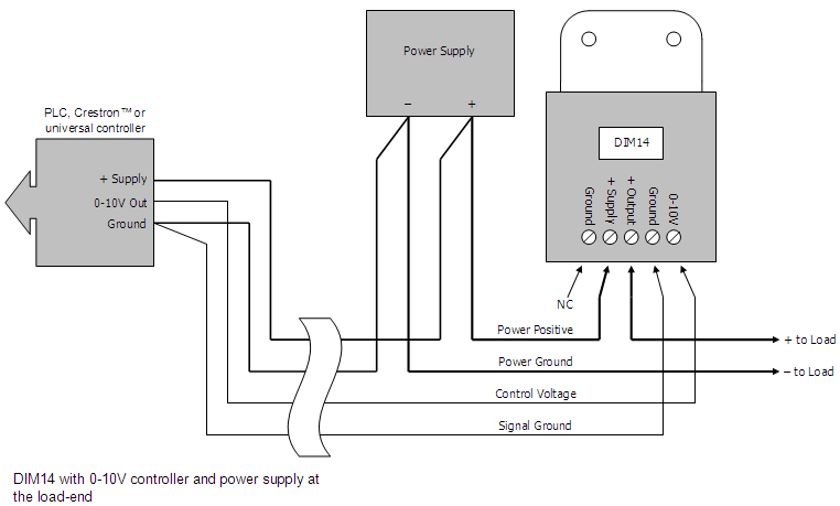
0-10v Dimmer Wiring What is 0-10V Dimming? very clear that class 1 and class 2 wiring can-not be combined. There must be separation. Because: a) it is possible for higher voltage wiring to induce an AC voltage in to the low voltage signal wiring; and, b) cause undesir-able visual artifacts in the dimmed lighting when the line and low voltage wiring is run.
0 10v Dimming Ballast Wiring Diagram - Diagram : Template ... 0 10 Volt Dimming Wiring Diagram. T12 Ballast Wiring Diagram. T12 To T8 Ballast Wiring Diagram. 2 Lamp T8 Ballast Wiring Diagram. 2 Lamp T12 Ballast Wiring Diagram. 4 Lamp 2 Ballast Wiring Diagram. 4 Lamp T12 Ballast Wiring Diagram. Bodine Ballast Wiring Diagram. F96t12 Ballast Wiring Diagram.
Divine 0 To 10 Volt Dimmer Wiring Diagram 4 Pole 3 Way ... A typical 0 10v wiring diagram is shown below. 0 10v dimming wiring diagram. Our standard 0 10v dimming driver option is often provided standard check spec sheets and dims down to 10 at minimum light level. Hot black typical 120v or 277v 60 hz neutral white. 0 10 volt dimmer switch wiring diagram print the electrical wiring diagram off and use ...
0 10v Dimming Ballast Wiring Diagram Collection - Wiring ... Wiring Diagram Pics Detail: Name: 0 10v dimming ballast wiring diagram - Dimming Ballast Wiring Diagram In Addition; File Type: JPG; Source: nhrt.info; Size: 106.48 KB; Dimension: 800 x 338; A Beginner's Guide to Circuit Diagrams. A first look at the circuit diagram might be confusing, in case look for a subway map, read schematics.
Kikker 5150 Wiring Diagram - 0 10 volt dimming wiring ... Kikker 5150 Wiring Diagram 0 10 volt dimming wiring diagram 2007 chrysler 300 master switch wiring diagram wiring diagram white 16.5 hp twin riding mower fridgidaire fridge replace light wiring diagram lexus sc300 rear tail light wiring diagram 1984 bayliner alternator wiring diagram 2017 f250 sony amp wiring diagram rockford fosgate r2-500x1 wiring diagram 6 v ford car radio wiring diagrams ...
0-10 Volt Dimming Wiring Diagram - Cadician's Blog 0 10 Volt Dimming Wiring Diagrams | Manual E-Books - 0-10 Volt Dimming Wiring Diagram Wiring Diagram arrives with several easy to adhere to Wiring Diagram Guidelines. It's intended to help all of the average consumer in creating a correct program. These guidelines will be easy to grasp and use.
Understanding 0-10v Dimmers for LED Light Fixtures When both wires are not touching, the dimming control output will be 10 volts, or 100%. When they are touching, the dimming control output will be 0 volts. 0 volts represents its minimum level, and depending on the driver, the fixture will either go into sleep mode, turn off completely, or utilize a dimmer switch to turn off.
Electronic Low Voltage Dimmer Wiring Diagram at Electronics 0 10 v lighting control dimmer wiring diagram system light switch angle electronics text png pngwing. Lutron diva dimmer for 0 10v led fluorescent fixtures single pole or 3 way white dvstv 453ph wh the. Unilight electric halo recessed lighting 0 10v led dimming info. This can result in having to pull additional wire on remodel projects. 0 to 10.
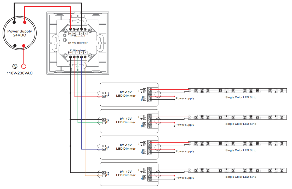
How to Wire LED 0 to 10V Dimming | Shine Retrofits ... These connect the dimming controller to one or more LED drivers that have the correct input for 0-10V dimming. All you must do then is connect the dimming controller with the appropriate wires to the LED driver. With the purple and grey wires installed at both ends, you'll have a 10 volt signal going out to your LED lights.
PDF 0 10 Volt Dimming Wiring Diagrams 0 10 Volt Dimming Wiring Diagrams 0 10 Dimming Ballast Wiring Diagram Pdf E books April 5th, 2019 - Ebook 0 10 Dimming Ballast Wiring Diagram currently available at kidsintow co uk for review only if you need complete ebook 0 10 Dimming Ballast Wiring Diagram please fill out registration form to access in our databases
0-10V Wire Colors to Change 0-10V dimming wires, the wires used to communicate dimming intensity via a 10-volt signal, can be easily identified on wiring diagrams, installation instructions, and dimmable drivers by their colors: gray and violet (although violet is often referred to as purple). This will soon change, however, as new codes and guidelines take effect.
Understanding 0-10V Dimming with Today's LED Commercial ... 0-10V dimming is a lighting control method that - on direct current voltage (DC) between 0 and 10 volts - can produce light at varying intensity levels. 0-10V dimming is the simplest control system for lighting, providing smooth operation and dimming down to 10%, 1%, and even 0.1% light level. At 10 volts, the light will go to maximum power.
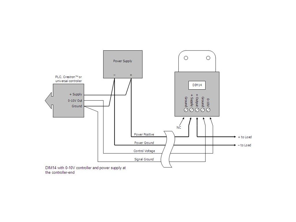

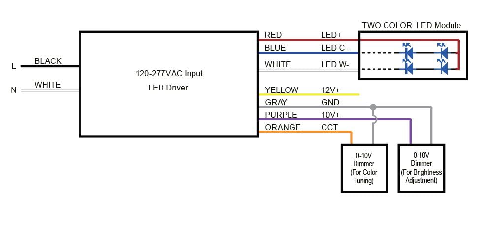


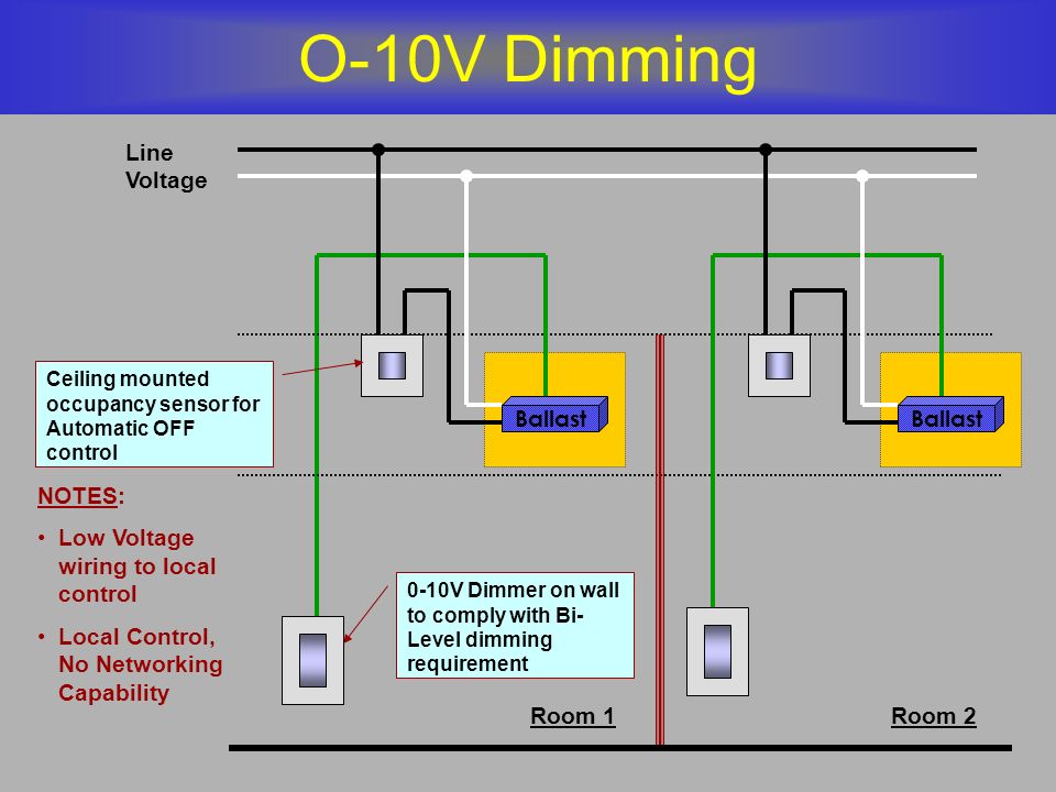













Comments
Post a Comment