41 allen bradley safety relay wiring diagram
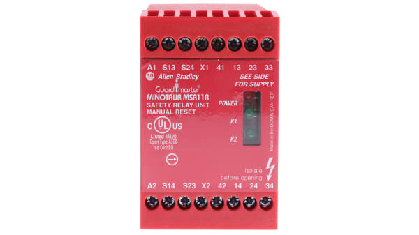
allen bradley guardmaster safety relay wiring diagram ... Allen Bradley Safety Relay Wiring Diagram - allen bradley guardmaster safety relay wiring diagram, allen bradley safety relay wiring diagram, Every electric structure consists of various distinct pieces. Each component ought to be placed and connected with other parts in particular way. If not, the… PDF Safety Relays - namratatradelinks.com The Allen-Bradley Guardmaster Minotaur MSR124RT is a safety monitoring relay that provides versatile inputs ... Reset and output monitoring are determined by the wiring configuration. Automatic/manual reset can use a ... Typical Wiring Diagrams 115/230V Supply, 24V DC Light Curtain, Monitored Manual Reset, Monitored Output ...
allen bradley safety control relay wiring diagram ... Find your allen bradley safety control relay wiring diagram here for allen bradley safety control relay wiring diagram and you can print out. Search for allen bradley safety control relay wiring diagram here and subscribe to this site allen bradley safety control relay wiring diagram read more!
Allen bradley safety relay wiring diagram
PDF Next Generation Guardmaster Safety Relay (GSR) Wiring Diagram Notes for Example Wiring Diagrams Note 1 In the wiring diagrams that are shown in this publication, the type of Allen-Bradley® Guardmaster® device is shown as an example to illustrate the circuit principle. For special applications, the choice of device type is based on the suitability of its characteristics for its intended use. Note 2 allen bradley co9 wiring/page/2 | Wirings Diagram Allen Bradley Safety Relay Wiring Diagram September 6, 2018 February 14, 2019 · Wiring Diagram by Hadir …Allen Bradley Guardmaster Safety Relays - Youtube - Allen Bradley Safety Relay Wiring Diagram Allen Bradley 440R-N23198 Msr30Rtp Guardmaster Safety Relay Single - Allen Bradley Safety Relay Wiring Diagram Bul…. Allen Bradley GuardMaster Safety Relay Wiring Tutorial ... Allen Bradley GuardMaster Safety Relay Wiring TutorialVisit for more Tutorials, Information & to connect with the CommunitySafety C...
Allen bradley safety relay wiring diagram. Allen Bradley 440R-N23198 Msr30Rtp Guardmaster Safety ... Watch The Video of allen bradley safety relay wiring diagram. Allen Bradley 440R N23198 Msr30Rtp Guardmaster Safety Relay Single - Allen Bradley Safety Relay Wiring Diagram Uploaded by Anna R. Higginbotham on Thursday, February 14th, 2019 in category Wiring Diagram. See also 440R S12R2 Ab Guardmaster Safety Relay, Single Input Pn 114859 ... 440R-S12R2 | Allen-Bradley Monitoring Safety Relay,Guardmaster,SI,Single Input,1 Dual Channel Universal Input, 1 N.C. Solid State Auxiliary Output Catalog #: 440R-S12R2 Lifecycle status: Active allen bradley safety relay wiring diagram | Wirings Diagram …Allen Bradley Guardmaster Safety Relays - Youtube - Allen Bradley Safety Relay Wiring Diagram Allen Bradley 440R-N23198 Msr30Rtp Guardmaster Safety Relay Single - Allen Bradley Safety Relay Wiring Diagram Bul…. PDF 700-2.14: Safety Relays - Rockwell Automation provides specifications for Allen-Bradley safety relays. For safety relay technical and application support, call 1-888-790-8377. ... Wiring Diagram and logic circuit for 700-ZBR520-- And 700-ZBR100--Figure 5 Safety Relay Operating Principle. 50 msec Max Legend 0 1 8 Safety Relays E-Stop Open
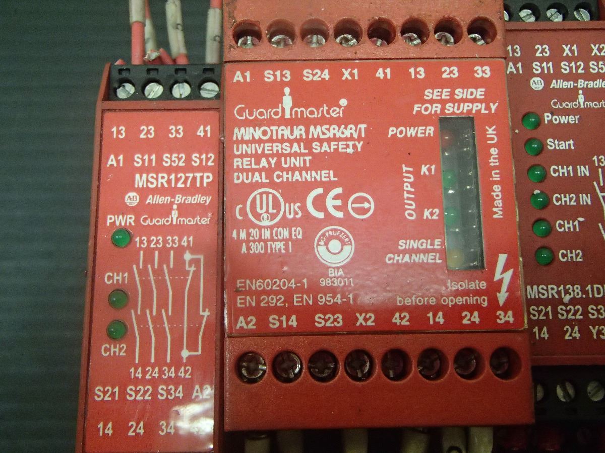
PDF Bul. 440R - Guardmaster Safety Relays (DI, DIS, SI, CI ... The single-wire safety connection simplifies cascading and expanding safety functions by linking relays with a single-wire connection. A dynamic signal from device to device provides a linkage in accordance with SIL 3, PLe, allowing easy addition of extra I/O, which can be configured with simple logic combinations. PDF Safety - MSR127RP/TP The safety outputs have independent and redundant internal contacts to support the safety function. The auxiliary output is a nonsafety output intended to provide an external signal about the status of the safety outputs. Features Category 4 per EN 954-1 Stop category 0 Three safety contacts One auxiliary contact Cross fault monitoring 440R-N23132 | Allen-Bradley Catalog #: 440R-N23132 Safety Relay,MSR127TP,24V AC/DC,Automatic/Manual,Removable,22.5MM,Infinite,One 2 N.C. Input,NO 1 N.O and 1 N.C. Input,No Safety Mat Inputs,One ... 440R Guardmaster Safety Relays | Allen-Bradley Provides versatility through simple logic, reset and timing configurations Includes single wire safety relay connection which allows for ease of installation and system flexibility Terminals are grouped together by power inputs and outputs for clear connection Offers compact solution which saves energy and space on DIN rail
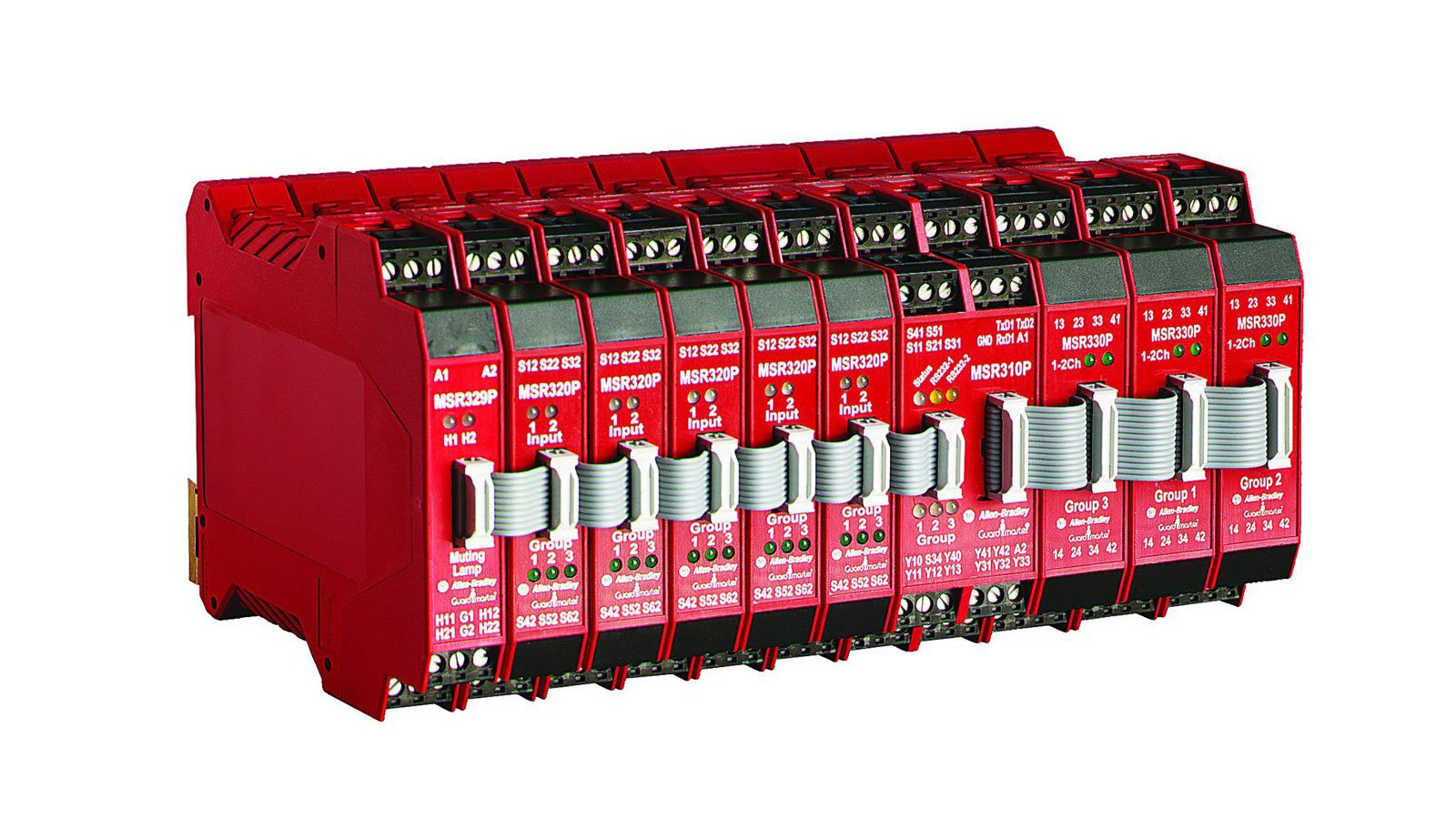
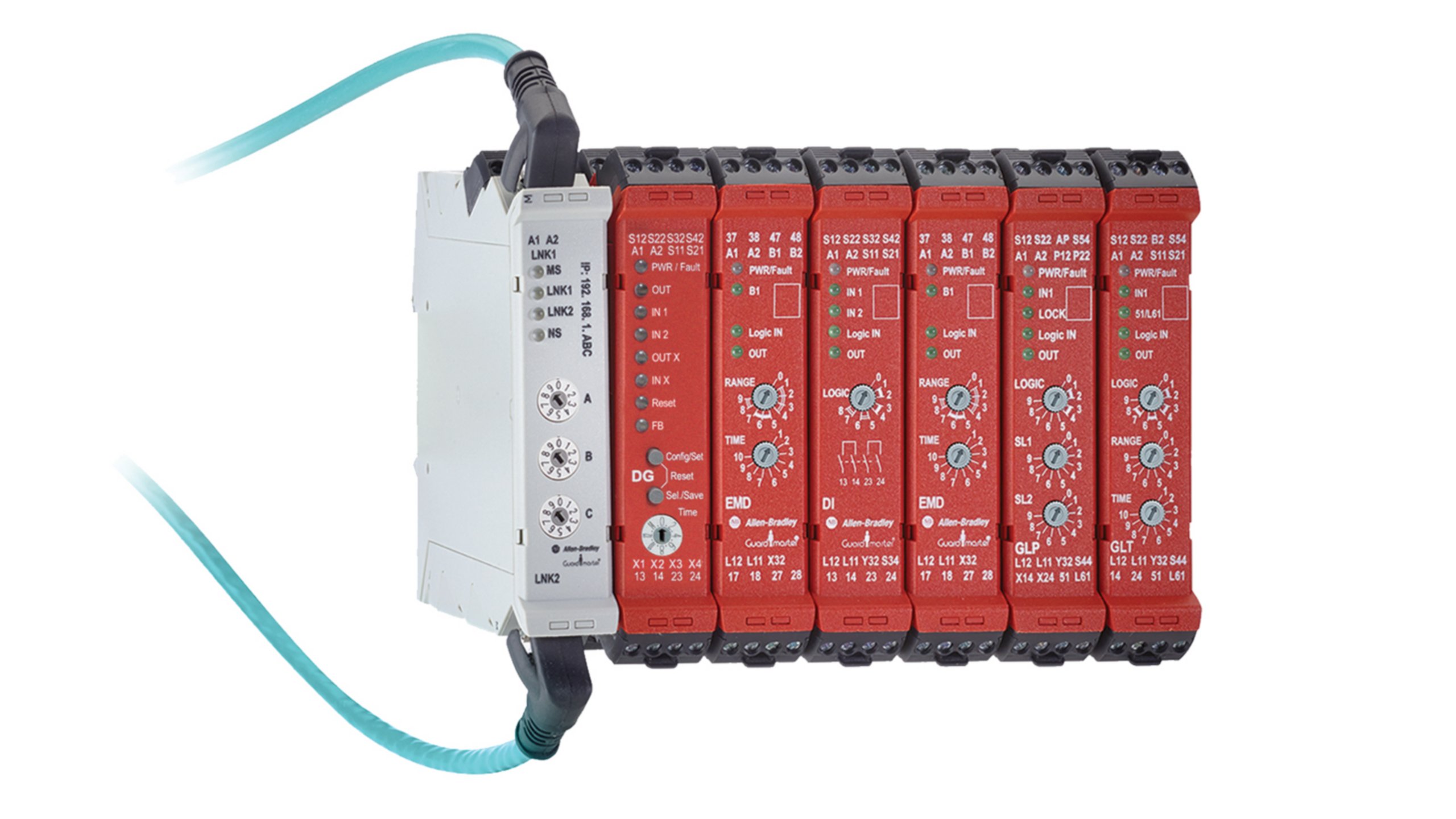
MSR300 Series Modular Safety Relays | Allen-Bradley Safety Relays, MSR300 Overview Allows connection of multiple input modules to a single base unit Includes logic configuration with multiple inputs and control of multiple independent outputs Performs simple function block logic configurations through rotary switch settings as opposed to software configuration Additional Information PDF Guardmaster Safety Relays User Manual This user manual addresses the CI, DI, DIS, EM, EMD, and SI safety relays from this family of relays. Hardware FeaturesFigure 1 - Safety Relays Removable Terminal Blocks Each relay module is only 22.5 mm (0.9 in.) wide with four removable terminal blocks (two on top and two on bottom). Allen Bradley Wiring Diagrams - Irish Connections Advantech wiring for allen bradley plc factory i o powerflex vfd instrumentationtools how to wire an compactlogix tw controls micro820 inputs and outputs or a micro800 micro830 micro850 micro870 magnetic starter 709 3 phase single 220v the hobby machinist diagram drawing rockwell automation png 504x583px allenbradley architecture area computer hardware devicenet circuit breaker contactor ... Allen Bradley GuardMaster Safety Relay Wiring Tutorial Step 1 - Power Off the Relay by Removing Power at the A1 and A2 terminals. Step 2 - Set the Rotary Switch to Position 0. Step 3 - Power ON the module by applying 24VDC on A1 and A2 terminals. Step 4 - Wait for the PWR LED to start flashing RED. Step 5 - Set the Rotary Switch to the desired position.
IEC Safety Control Relays | Allen-Bradley
Allen Bradley Wiring Diagrams - Wiring Diagram Line Allen Bradley Wiring Diagrams Wiring Diagram Line Wiring Diagram ... problem 6 draw following chegg com 800 0 typical push on control stations asi equivalent 700 hlt1z24 terminal block relay safety tutorial power flex basic setup plc247 installation instructions professional 1771 ibn c digital module supplier manufacturer amikonltd undated b ...
How do you scale up safety devices? : r/PLC
PDF Safety - MSR126R/T The Allen-Bradley Guardmaster Minotaur MSR126R/T is a safety monitoring relay that provides the very basics for safety control ... Safety Classification Cat. 4 per EN 954-1 (ISO 13849-1), SIL CL3 per EN IEC 62061, PLe per ISO 13849-1 ... Typical Wiring Diagrams. 115/230V Supply, 24V DC Light Curtain, Monitored Manual Reset, Monitored Output

Award-Winning Guardmaster 440C-CR30 Safety Relay Eases Programming
Allen-Bradley PointIO Safety Modules Wiring and ... Diagram 1.1-Allen Bradley 1734-IB8S module Safety PointIO Hardware Overview & Wiring. The 1734-IB8S and OB8S are 8-point modules for their respective inputs or outputs. Looking at these modules we notice they have 16 channels available with similar wiring schemes. However, the difference is in the test points on the 1734-IB8S safety input module.

Rockwell / Allen-Bradley 440N-C02068 Ferrocode Coded Magnetic Safety Switch & Control Unit
PDF Guardmaster Configurable Safety Relay Wiring Diagram Guardmaster Configurable Safety Relay Catalog Number 440C-CR30-22BBB Wiring Diagram Important User Information Read this document and the documents listed in the additional resources section about installation, configuration, and operation of this equipment before you install, configure, operate, or maintain this product.
Safety Relays | Allen-Bradley
PDF MSR127 Minotaur Monitoring Safety Relays Installation ... MSR127 Minotaur Monitoring Safety Relays Installation Instructions Approximate Dimensions Figure 3 - Dimensions [mm (in.)] Installation 1. Mount in enclosure (minimum rating of IP54). 2. To remove terminals (P versions only), insert a screwdriver and slowly move as shown. Safety Specification
440R-J23044 | Allen Bradley Guardmaster Minotaur 24V ac/dc ...
Safety Relays | Allen-Bradley - Rockwell Automation Our Single-function and Specialty Relays are designed to provide basic and advanced safety functions such as time delays and speed monitoring. They are also designed to be used in specific applications such as two-hand control, muting, and the control of pressure-sensitive safety mats and edges. Product Details Safety Control Relays
Safety Relays | Allen-Bradley
wiring of safety relay | Wirings Diagram Tags: 1996 7.3 powerstroke glow plug relay wiring diagram, 1997 7.3 powerstroke glow plug relay wiring diagram, 2000 7.3 powerstroke glow plug relay wiring diagram ...
Guardmaster Safety Relays User Manual
PDF Safety Relays - Namrata Trade Links Light curtain, E-stop, safety gate inputs Two immediate safety outputs Delayed outputs: 3 N.O. safety or 2 N.C. safety and 1 N.C. aux. Cross fault monitoring Monitored or automatic reset Removable terminals LED Indicators Green 3RZHU³,OOXPLQDWHVZKHQSRZHURQ Green 6WDUW³,OOXPLQDWHVZKHQ6 6 LVFORVHG Green &+ ,1³,OOXPLQDWHVZKHQFKDQQHO LQSXWLVFORVHG

Wiring safety relay SRB301 and emergency stop.
Allen Bradley 700 Relay Wiring Diagram - GORGEOUS DIAGRAM Allen bradley 700 relay wiring diagram. It shows the components of the circuit as simplified shapes and the gift and signal contacts along with the devices. Our Bulletin 700-N Industrial Relays are a low profile high reliability switching solution. A wiring diagram usually gives counsel virtually the relative slant and concord of devices.

440RD22R2 AB | Allen-Bradley 440R-D22R2- CBT Company ...
Allen Bradley GuardMaster Safety Relay Wiring Tutorial ... Allen Bradley GuardMaster Safety Relay Wiring TutorialVisit for more Tutorials, Information & to connect with the CommunitySafety C...
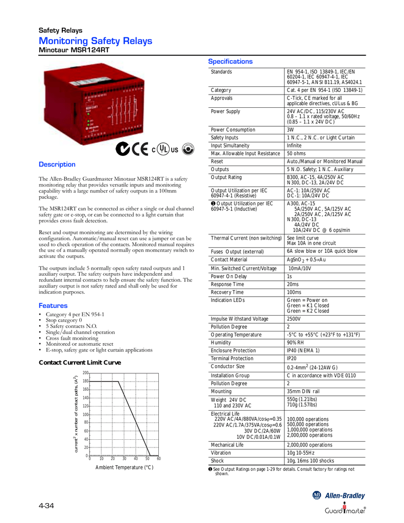
ALLEN-BRADLEY MSR124RT
allen bradley co9 wiring/page/2 | Wirings Diagram Allen Bradley Safety Relay Wiring Diagram September 6, 2018 February 14, 2019 · Wiring Diagram by Hadir …Allen Bradley Guardmaster Safety Relays - Youtube - Allen Bradley Safety Relay Wiring Diagram Allen Bradley 440R-N23198 Msr30Rtp Guardmaster Safety Relay Single - Allen Bradley Safety Relay Wiring Diagram Bul….
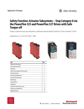
Safety Function: Actuator Subsystems – Stop | Manualzz
PDF Next Generation Guardmaster Safety Relay (GSR) Wiring Diagram Notes for Example Wiring Diagrams Note 1 In the wiring diagrams that are shown in this publication, the type of Allen-Bradley® Guardmaster® device is shown as an example to illustrate the circuit principle. For special applications, the choice of device type is based on the suitability of its characteristics for its intended use. Note 2
440R Guardmaster Safety Relays | Allen-Bradley

WELCOME TO SAFETY RELAYS 101 BASIC OPERATION AND FUNCTIONS ...

Next Generation Guardmaster Safety Relay (GSR) - PDF Free ...

Emergency Stop Circuit - PLCS.net - Interactive Q & A

Guide to Safety Relays and Safety Circuits
Guardmaster Safety Relays Brochure
Guardmaster Configurable Safety Relay Wiring Diagram
External Safety Relay - Fanuc Robot Forum - Robotforum ...

440RS13R2 AB | Allen-Bradley 440R-S13R2- CBT Company ...
WELCOME TO SAFETY RELAYS 101 BASIC OPERATION AND FUNCTIONS ...
Safety Function: SensaGuard Non-contact Interlock Switch with ...

What is Safety Relay PILZ ? Easy Explained | pnoz X2 X3 X4
Door Monitoring Interlock Switch with a Safety Relay and ...
Safety Relays | Allen-Bradley
440R-S07282 | Allen Bradley Guardmaster Safety Relay - With 2 ...

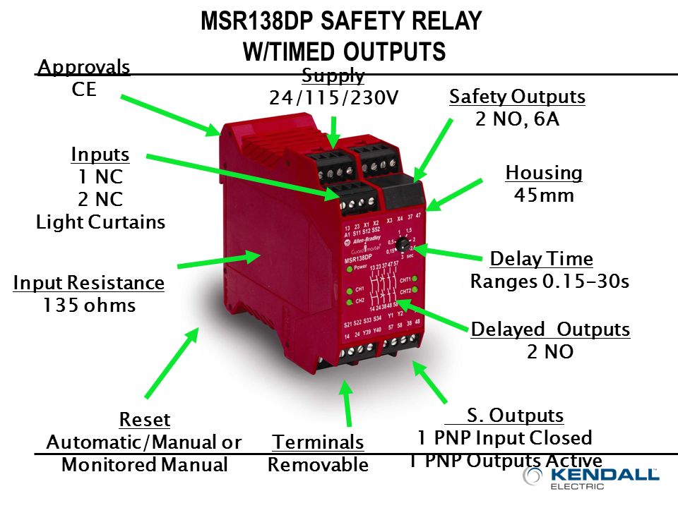
Safety Relay Guardmaster 440R-M23141 Allen-Bradley MSR138DP ...

Guide to Safety Relays and Safety Circuits
Single-function Safety Relays with Delayed Outputs | Allen ...

Allen-Bradley Guardmaster 440R-N23213 MSR127 Safety Relay, 24 ...

Allen Bradley 440R-N23129 MSR127R Guard Mater Safety ...
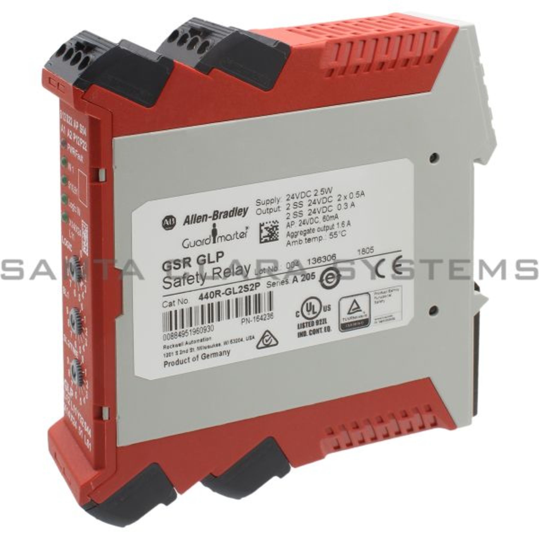
440R-GL2S2P Allen Bradley Safety Relay - Santa Clara Systems
Allen-Bradley GuardMaster Safety Relays

60 Lovely Allen Bradley Guardmaster Safety Relay Wiring ...

700S-CF530KFC Allen Bradley | Allen Bradley 700S-CF 8 Pole ...

70 Lovely Idec Relay Wiring Diagram | Relay, Electromagnet ...
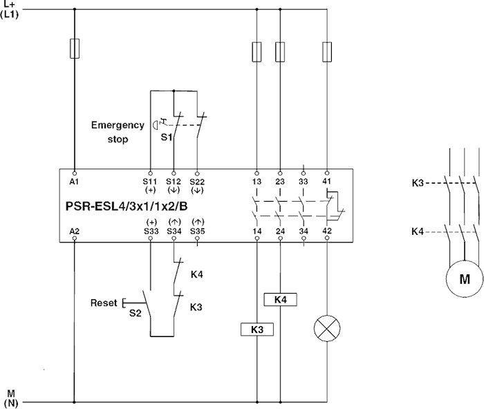
Phoenix Contact 2981059 PSR-SCP- 24UC/ESL4/3X1/1X2/B safety relay, 24VAC/DC, screw

440R-S13R2 - Guardmaster Compatibility Input Safety Relay (CI ...

Interlock Architectures – Pt. 4: Category 3 - Control Reliable
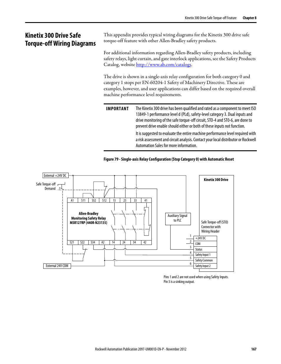
Kinetix 300 drive safe torque-off wiring diagrams | Rockwell ...


Comments
Post a Comment